


10
DVRT41 Direct Vent Gas Fireplace
10006740
FP1031
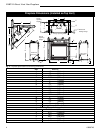
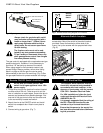
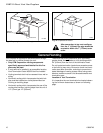
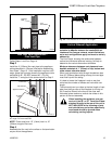
Fig. 13 Completed conversion.
After conversion to top vent configura-
tion, the 4” (102mm) flue pipe should be
concentric within the 7” (175mm) outer
collar.
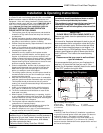
Your fireplace is approved to be vented either through
the side wall, or vertical through the roof.
• Only CFM Corporation venting components
specifically approved and labelled for this fire-
place may be used.
• If vent terminal is installed in an accessible location,
Vent Termination Guard #53525 shall be installed.
• Venting terminals shall not be recessed into a wall or
siding.
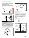
• Horizontal venting which incorporates the twist lock
pipe must be installed on a level plane without an
inclining or declining slope.
• Horizontal venting which incorporates the use of flex
venting shall have an inclining slope from the unit of
1/2” (13mm) per 12” (305mm).
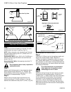
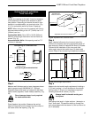
There must not be any obstruction such as bushes,
garden sheds, fences, decks or utility buildings within
24" (610mm) from the front of the termination hood.
Do not locate termination hood where excessive snow
or ice build up may occur. Be sure to check vent termi-
nation area after snow falls, and clear to prevent acci-
dental blockage of venting system. When using snow
blowers, make sure snow is not directed towards vent
termination area.
Location of Vent Termination
It is imperative the vent termination be located observ-
ing the minimum clearances as shown on following
page.
General Venting
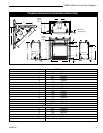
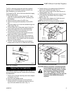
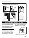
Flue Cover
Replace
Screws (4)
Flue Pipe
FP1028
Fig. 12 Replacing flue cover and flue pipe.
Replace
Screws (4)