


15
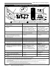
DVRT41Direct Vent Gas Fireplace
10006740
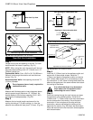
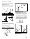
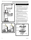
Finished
Wall
Vent
Termination
Fig. 23 Side view of final unit location.
FP1005
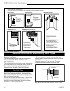
Vertical Sidewall Application
Since it is very important that the venting system
maintain its balance between the combustion air
intake and the flue gas exhaust, certain limitations
as to vent configurations apply and must be strictly
adhered to.
The Vent Graph, showing the relationship between
vertical and horizontal side wall venting, will help to
determine the various dimensions allowable.
Minimum clearance between vent pipes and com-
bustible materials is 1” (25mm) on top, bottom and
sides unless otherwise noted.
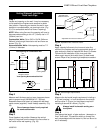
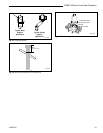
When vent termination exits through foundations less
than 20” (508mm) below siding outcrop, the vent pipe
must flush up with the siding.
It is best to locate the fireplace in such a way that
minimizes the number of offsets and horizontal vent
length.
The horizontal vent run refers to the total length of vent
pipe from the flue collar of the fireplace (or the top of
the Transition Elbow) to the face of the outer wall.
Horizontal plane means no vertical rise exists on this
portion of the vent assembly.
When installing the appliance as a rear
vent unit, the 90° or 45° Transition Elbow
attached directly to the rear of the unit is
NOT INCLUDED in the following criteria
and calculations, and unless specifically
mentioned should be ignored when
calculating venting layouts.
Rear Wall Vent Installations -
Flex Vent Pipe
Follow Steps 1 and 2 on Page 14.
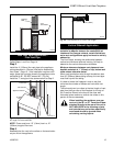
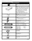
Step 3
Install the 4” (102mm) flex vent pipe to the appliance
collars described in “General Information Assembling
Vent Pipes”, Page 12. If the installation requires a 45°
angle, grasp the vent pipe close to the appliance collar
and bend to 45°. DO NOT exceed 45°. (Fig. 24)
Install the 7” vent pipe in the same manner as Step 2.
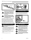
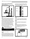
Termination
Flex Section
Appliance Collars
FP1473
Fig. 24 Grasp the vent pipe close to the collar and bend to
45° angle. Do not exceed 45°.
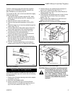
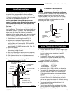
NOTE: There must be a 1/2” (13mm) rise in a 12”
(305mm) length of flex vent.
Step 4
Assemble the flex vent to the collars on the termination
as you did on the appliance.
1/2" (13mm)
12" (305mm)
FP1472
Fig. 25 There must be a 1/2” rise in 12s” length.