


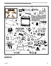
36
DVRT41 Direct Vent Gas Fireplace
10006740
Fuel Conversion Instructions
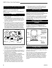
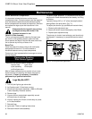
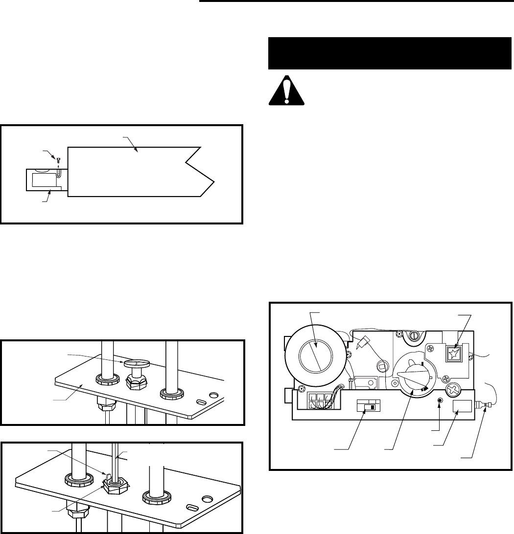
Honeywell Comfort Control Valve ONLY
WARNING: The conversion must only be
undertaken by a qualified, certified gas
appliance installer.
LOCAL
REMOTE
O
N
¥
PILOT
OFF
¥
LED
Motor Top Cap
Piezo Ignitor
Local/
Remote Switch
Pilotstat
Knob
LED
Plug
Antenna
FP1037
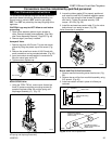
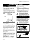
Fig. 64 Comfort control valve.
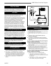
Fig. 63 Remove pilot orifice.
CO106a
Snap Ring
Index Tab
Allen
Wrench
Fig. 62 Remove pilot hood.
CO105a
Pilot Hood
Pilot Bracket
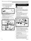
4. Remove air shutters from burner pan by removing
shutter retaining screw then air shutter. (Fig. 61)
5. For DVRT41 replace only rear air shutter.
Natural Gas: Rear air shutter, close half.
Front air shutter, fully open.
LP: Rear air shutter fully open.
Front air shutter fully open.
6. Re-install manifold to burner pan.
NOTE: It is not necessary to remove the pilot tube
for conversion.
7. Remove pilot hood by lifting up. (Fig. 62)
8. Remove pilot orifice with allen wrench. (Fig. 63)
9. Install conversion pilot orifice.
10. Re-install pilot hood and be sure to align with index
tab. Installation is complete.
Burner Pan
Shutter
Retaining
Screw
Air
Shutter
Front View
CO103
Fig. 61 Remove air shutter from burner pan.
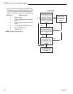
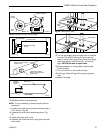
Installation Precautions
Before proceeding, turn control knob on valve to OFF
and turn gas supply OFF. Turn OFF any electricity that
may be going to the appliance. CAUTION: Logs may
be hot!
Conversion Procedure
1. Open bottom grille to gain access to valve. Remove
glass door. (Refer to “Window Frame Assembly
Removal Section” Page 23, Fig. 46)
2. Remove logs if previously installed. CAUTION:
Logs may be hot!
3. Remove and replace plug on lower right hand side of
the valve; Red for LP and blue for NG. (Fig. 64)
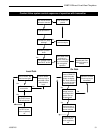
4. Remove motor top cap. Depress and turn center
plunger until arrow points to correct screw. Red for
LP and Blue for NG. NOTE: Plunger will “snap” into
NG position when arrow is close to blue screw. It will
not “snap” at LP (Red) position. (Fig. 65)
5. Remove manifold mounting screw. (Fig. 66)
6. Remove burner orifice from manifold assembly using
7/16” wrench. (Fig. 67)
7. Install conversion orifice in place of orifice just
removed. Refer to Table 2.
8. Remove both air shutters from burner pan by
removing air shutter retaining screw then air shutter.
(Fig. 68)
9. Install conversion air shutters on burner pan. Re-
place air shutter retaining screw. Adjust both air
shutters. Refer to Table 3 for proper air shutter
adjustment. Secure air shutter retaining screw.