


9
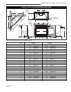
DV360/580 Series Direct Vent Gas Fireplace
20010667
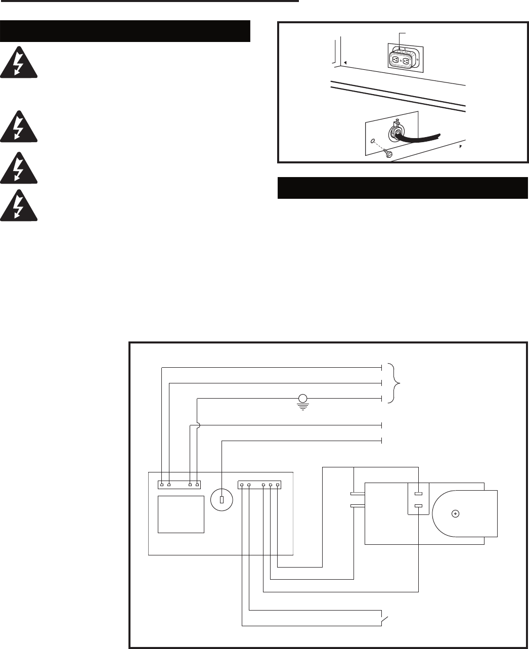
EB-1 Electrical Box
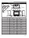
The fireplace, when installed, must be
electrically connected and grounded in
accordance with local codes or, in the ab-
sence of local codes, with the current CSA
C22.1 Canadian Electrical Code.
For USA installations, follow the local
codes and the national Electrical Code
ANSI/NFPA No. 70.
It is strongly suggested that the wiring of
the EB-1 Electrical Junction Box be carried
out by a licensed electrician.
Ensure that the power to the supply line
has been disconnected before commenc-
ing this procedure.
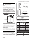
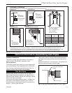
The EB-1 electrical junction box has been
supplied standard on the DV360/580 models to allow
for the easy installation of an optional fan kit.
To connect the EB-1 box to the house electrical supply,
follow the steps below.
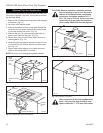
1. Unscrew the retaining screw from the EB-1 base
plate (Fig. 9) and remove the EB-1 assembly from
the fireplace.
2. Remove the front cover of the EB-1 box.
3. Remove the plug socket
assembly from the EB-1
box.
4. Feed the supply line in
from the outside through
the cable clamp. (Fig. 9)
5. Connect black wire of
the power supply line to
the brass screw (polar-
ized) of the socket as-
sembly.
6. Connect the white wire
of the power line to the
chrome screw of the
socket assembly.
7. Connect the ground
wire of the supply line to
the green screw of the
socket assembly.
8. Refit the socket assem
-
bly back into the electri-
cal box and replace the
cover plate. Secure the
cable with the clamp on
the outside of the unit
to prevent strain on the
connections.
9. The EB-1 electrical junction box is now ready to sup
-
ply power to the FK12 or FK24 fan kits if fitted.
FP580
INSTA VENT FREE
EB1 JUNCTION BOX
11/18/97
OUTSIDE
Electrical Box
FRONT OF UNIT
INSIDE
FRONT OF UNIT
FP580
Fig. 9 EB-1 receptacle.
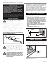
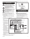
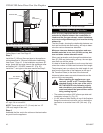
Electronic Gas Control Valve
This appliance may be fitted with a Synetek ignition
module.
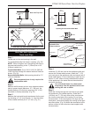
Installation of the remote on/off starter switch or
wall thermostat on electronic ignition units.
1. Thread the wiring through the holes on the side
panels of the appliance. Take care not to cut the wire
or insulation on metal edges. Route the wire to a
conveniently located receptacle box.
2. Attach the wire to the ON/OFF switch and install the
switch into the receptacle box.
POWER CORD
CIRCUIT BOARD
ON/OFF SWITCH
OR
WALL THERMOSTAT
VALVE
RED
WHITE
BLUE
YELLOW
PURPLE
BLACK
WHITE
GREEN
PILOT SENSING
PILOT IGNITER
ORANGE
L1
L2
M
O
P
O
FP1571
SIT822
Synetek wiring
4/05
Fig. 10 SIT822 Valve with Synetek electronic control wiring diagram.
FP1571