


19
DV360/580 Series Direct Vent Gas Fireplace
20010667
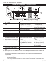
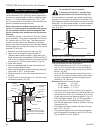
Step 7
Apply high temperature sealant to 4” (102 mm) and
7” (178 mm) collars or the termination one inch away
from crimped end. Guide the vent terminations 4” and
7” collard into their respective vent pipes. Double check
that the vent pipes overlap the collars by 2” (51 mm).
Secure the termination to the wall with screws provided
and caulk around the wall plate to weatherproof. As an
alternative to screwing the termination directly to the
wall, you may also use expanding plugs or an approved
exterior construction adhesive. You may also attach the
termination with screws through the inner body into the
4” vent pipe, however for this method, you must extend
the 4” pipe approximately 6” (152 mm) beyond the outer
face of the wall.
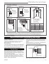
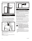
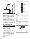
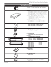
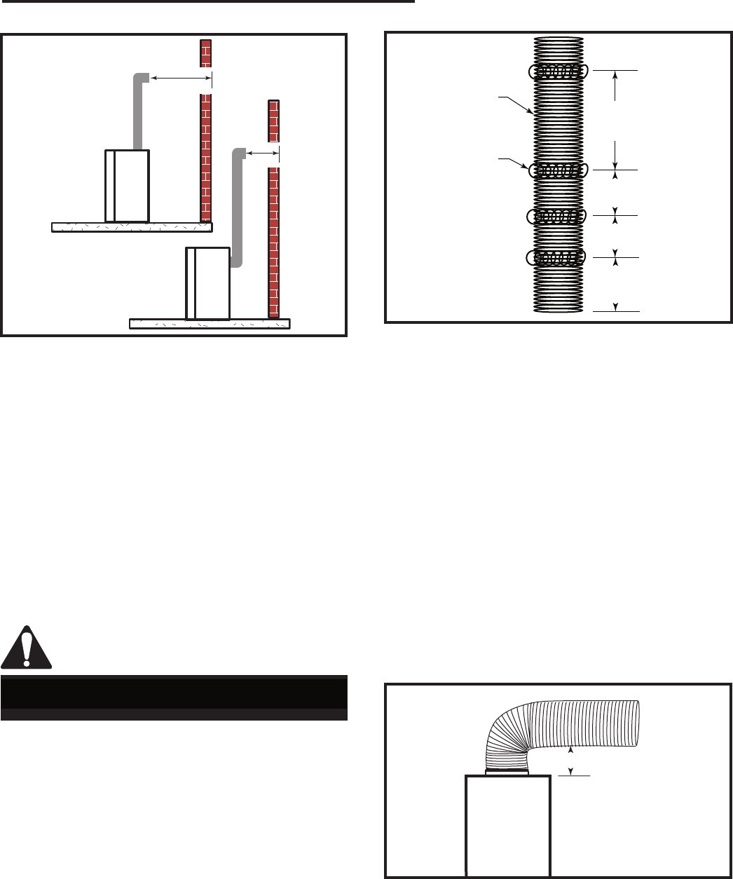
Support horizontal pipes every 36”
(914 mm) with metal pipe straps.
X
X
FP1182
Fig. 35 Horizontal length requirement.
Vertical Sidewall Installation
Flex Vent Pipe
NOTE: The 40” (1016 mm) flex vent is used for 90° off
the top of the unit then out the back wall.
Follow Step 1 and 2 on Page 18.
Step 3
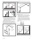
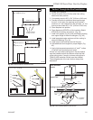
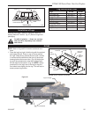
Install the four (4) spacer springs on the 4” flex vent
pipe. When installing the spacer springs around the 4”
pipe, stretch the spring to approximately 15” (381 mm),
wrap the spring around the pipe and interlock the ends
of the spacer spring approximately 2” (51 mm). Mea-
sure 6³⁄₄” (172 mm) from the end of the pipe. Place the
next spring 5” (127 mm) from the previously installed
spring. Place the next spring 6” (152 mm) from the last
spring. Finally place the last spring 12” (305 mm) from
the last spring installed. (Fig. 36)
12"
(305mm)
6"
(152mm)
5"
(127mm)
6³⁄₄"
(172mm)
FP1474
spacer springs
4/04 djt
4” Flex Vent Pipe
Spacer Spring
FP1474
Fig. 36 Install spacer springs.
Step 4
Install the 4” (102 mm) flex vent pipe to the appliance
collar as described on Page 13. Secure the end with the
first spring 6³⁄₄” (172 mm) from the flex pipe end to the
unit.
Step 5
Slide the 7” (178 mm) flex vent pipe over the 4” flex
vent pipe and secure the 7” collar as described on Page
13.
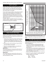
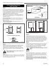
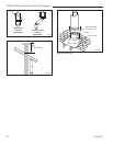
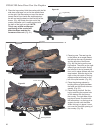
Step 6
Bend the flex pipe horizontal so the bottom of the hori-
zontal pipe measure 6¹⁄₂” (165 mm) from the top of the
unit immediately after the 90° formation. (Fig. 37) Be
sure to follow the 1/2” (13 mm) rise in a 12” (305 mm)
horizontal run rule.
Step 7
Install the 4” flex then 7” flex to the termination.
6¹⁄₂" (165mm)
FP1475
flex 90 bend
4/04 djt
FP1475
Fig. 37 Bend flex vent at 90° so horizontal portion is 6¹⁄₂”
(165 mm) off top of unit.