66
10005898
Vermont Castings, Majestic Products, DEF33/36, DEFD33/36
Electrical outlet wiring must comply with
local building codes and other applicable
regulations to reduce the risk of fire,
electrical shock and injury to persons.
Electrical Connection
A 15 AMP, 120 Volt, 60 Hz circuit with a properly
grounded outlet is required. Preferably, the fireplace
will be on a dedicated circuit as other appliances on
the same circuit may cause the circuit breaker to trip or
the fuse to blow when the heater is in operation. The
unit comes standard with a 6 ft.
(1828
mm) long three
wire cord, exiting the right side of the fireplace. Plan
the installation to avoid the use of an extension cord. If
an
extension
cord
is
used,
it
must
be
minimum
14
AWG,
three-wire with grounding type plug and connector,
rated not less than 1875 Watts. This extension cord
shall not be more than 20 feet (508
mm) in length.
If permitted by local codes, a new electrical outlet may
be installed inside the frame construction.
Do not use this fireplace if any part of it
has been under water. Immediately call a
qualified service technician to inspect
the fireplace and to replace any part of
the electrical system which has been
under water.
Hard (Direct) Wire Connection
If desired, a qualified electrician may remove the cord
connection and wire this unit directly to the household
wiring. See page 15.
Any electrical rewiring of this appliance
must be done by a qualified electrician.
This wiring must be done in accordance
with local codes and/or in Canada with
the current CSA C22.1 Canadian
Electrical code, and for U.S.A.
installation, National Electrical Code
ANSI/NFPA Nº 70.
WARNING: This fireplace comes with
a manual circuit breaker reset beside
the ON/OFF switch. In case the fireplace
is not operating, check the circuit breaker
and reset the button at the breaker. If the
fireplace is still not operating,
immediately
call a qualified service technician to
inspect the fireplace.
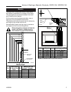
C
A
B
Adjustable Drywall Strip
(Nailing Flange)
Screw Drywall
Position Depths
A 1/2" / 13mm
B 5/8" / 16mm
C 3/4" / 19mm
Adjustable 1/2",
5/8", 3/4"
Spacing
FP1023
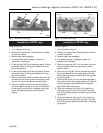
Fig. 3 Adjustable drywall strip (nailing flanges)
1. Choose fireplace location.
2. Place fireplace into position.
3. Frame in fireplace with a header across the top. It is
important to allow for finished face when setting the
depth of the frame.
4. Attach fireplace to frame using adjustable frame
drywall strips (Fig. 3). Preset depth to suit facing
material—adjustable to
1
/
2
",
5
/
8
" or
3
/
4
" depths
(Fig. 3).
5. Screw through slotted holes in drywall strip, then
screw into pre-drilled holes on fireplace side.
Measure from face of fireplace to face of drywall
strip to confirm the final depth (Fig. 3).
Framing and Finishing


