


15
10005898
Vermont Castings, Majestic Products, DEF33/36, DEFD33/36
Direct (Hard) Wiring
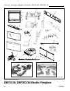
Electric Fireplace Models
DEF33/ DEF36/ DEF36S2
WARNING:This procedure must be conducted by a
qualified electrician, in accordance with National and
local codes. In the U.S.A., the installation must
conform to the National Electrical Code, ANSI/NFPA
No. 70. In Canada, the installation must conform to the
current CSA C22.1 Canadian Electrical Code.
WARNING: Make sure the power to the unit is off, and
the power cord is unplugged from the wall outlet before
proceeding with this conversion. Failure to do so may
result in property damage, personal injury or loss of life.
This instruction is intended as a guide for replacing the
power cord supplied with Models HEF33/DEF33/
DEF36/DEF36S2 electric fireplace with direct (hard)
wiring.
NOTE: When direct wiring this appliance, it must be
connected to a 15 Amp dedicated circuit breaker or
fuse in the electrical panel of the dwelling. The cable
between the circuit/fuse panel and the fireplace must
meet all local and national codes, and in no case shall
the wires be less than 14 gauge.
1. Make sure the power to the unit has been turned
off, the power cord is unplugged from the wall outlet
and the unit has cooled down if it has been
operating.
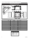
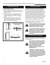
2. Lower the bottom louvre panel to expose the
control panel.
3. Using a phillips screwdriver, remove the two screws
on the side tabs of the control panel that secure the
panel to the cabinet.
4. Grasp the tabs on the control panel and gently lean
the top of the panel towards you while lifting it up
until the locking tabs on the bottom of the control
panel are disengaged from the bottom of the unit.
Lay the control panel face down on top of the louvre
panel. Do not force the panel, as this may result in
wires being disconnected from their controls.
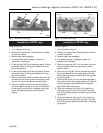
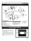
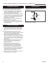
5. Locate where the power cord enters the control
compartment on the right hand side of the unit.
Using wire cutters, cut the power cord within three
inches (75mm) of the point where it exits the
cabinet.
6. Carefully separate the three wires of the power cord
into separate wires by gently pulling them apart.
DO NOT use a knife, as this may expose bare
conductor. The hot wire is connected to the circuit
breaker. The neutral wire is connected to the rocker
switch and the green ground wire is attached to a
ground stud on the rear panel of the control
compartment.
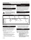
7. Using wire strippers, strip approximately
5
/
8
"
(15 mm) from the ends of the hot and neutral wires.
8. Using a wrench, remove the #10-24 hex nut from
the ground stud where the green wire from the
power cord is attached. Remove and discard the
green wire. Reinstall the nut but do not tighten yet.
9. Standing on the right side of the unit, locate the
power cord where it exits the cabinet. Using pliers,
gently cut and remove the power cord. Dispose of
the power cord.
10. Using a slotted screwdriver, remove the
7
/
8
"
(22 mm) diameter knockout from the right hand side
of the cabinet below where the strain relief was
located.
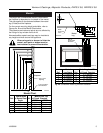
11. Route the electrical cable from the breaker/fuse
panel through the
7
/
8
" (22 mm) diameter hole and
secure to the cabinet using an approved clamp.
The power wires should extend approximately
6" (152 mm) into the control compartment.
WARNING: Make sure the power to the power cable
has been turned off at the breaker/fuse panel of the
residence before proceeding.
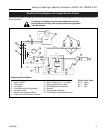
12. Connect the ground wire form the power cable by
wrapping it around the ground stud of the unit and
securing it using the #10-24 nut.
13. Using a wire nut, connect the hot lead (black), of
the power cable to the power cord wire leading to
the circuit breaker on the control panel. Similarly,
connect the neutral wire (white), of the power cable
to the power cord wire leading to the rocker switch,
using a wire nut. It is recommended that the wire
nuts be taped to the wires, using electrical tape, as
an extra safety measure.
14. Visually check that none of the wires in the control
compartment have been dislodged from the
controls. If they have, use the wiring diagram on
the unit or in the instruction manual to replace
them in their proper location.
15. Reinstall the control panel and secure it using the
screws removed in step 3. Make sure that wires do
not become pinched when replacing the panel.
16. Make sure that the rocker switch on the control
panel is in the off position. Turn the power to the
unit on at the breaker/fuse panel. Place the unit into
operation and check to make sure that all of the
systems are working properly.