


- 14 -
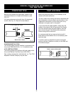
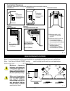
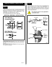
COMBUSTIBLE WALLS (Fig. 25): Cut a 9-3/8"H x 9-3/8"W (240
mm x 240 mm) hole through the exterior wall and frame as shown
(Fig. 24).
NON-COMBUSTIBLE WALLS (Fig. 25): Hole opening must be
7.5" (190 mm) in diameter.
(240mm)
9-
3/8
"
9-
3/8
"
(240mm)
7-
1/2
"
(190mm)
Vent Opening —
Combustible Wall
Vent Opening —
Noncombustible Wall
(framing detail)
Fig. 25
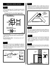
STEP 1
Locate vent opening on the wall. It may be necessary to first
position the fireplace and measure to obtain hole location.
Depending on whether the wall is combustible or non-
combustible, cut opening to size. Fig. 25.
(For combustible walls first frame in opening).
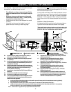
VERTICAL SIDEWALL INSTALLATION
VERTICAL SIDEWALL APPLICATION
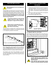
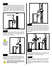
STEP 2
Fig. 26. Measure wall thickness and cut adjustable zero
clearance sleeve parts to proper length (MAXIMUM 12"/
305mm). Adjust sleeve to minimum (9-3/8" x 9-3/8") and
attach to firestop with #8 sheet metal screws (supplied).
Install firestop assembly.
Zero clearance sleeve is only required for
combustible walls.
Fig. 26
#8
SCREWS(2)
ADJUSTABLE ZERO
CLEARANCE SLEEVE
ADJUSTABLE
ZERO CLEARANCE
SLEEVE
#8
SCREWS(2)
#8
SCREWS(2)
Maximum Length
12" (294mm)
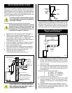
FIRESTOP
WOOD FRAMING
WALL EXTERIOR
VENT PIPE
FIRESTOP
ZERO
CLEARANCE
SLEEVE
FLUSH WITH
WALL
EXTERIOR
DRYWALL