


- 13 -
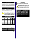
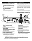
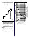
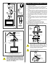
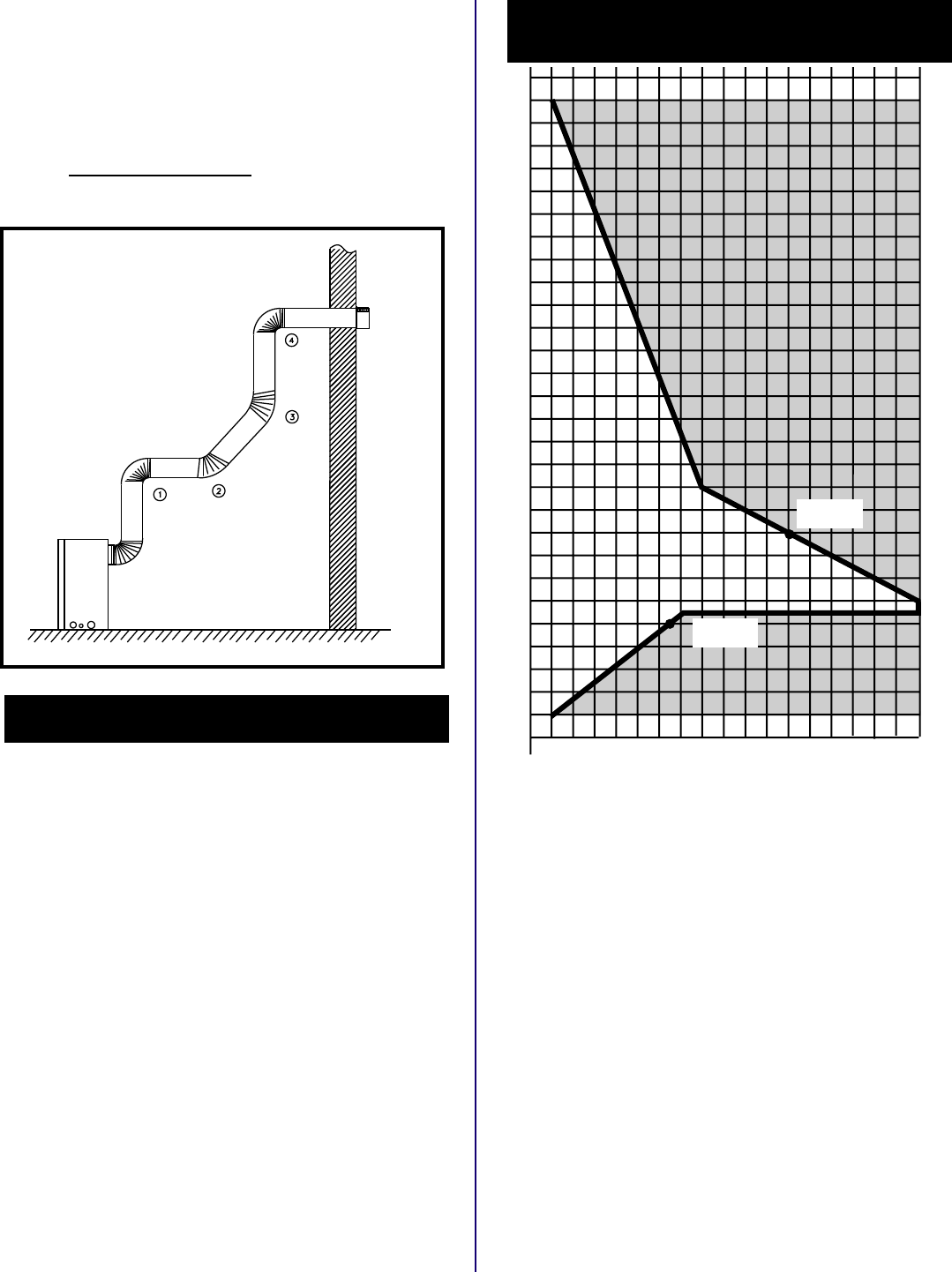
HORIZONTAL DIMENSION
SEE PAGE 15 FOR VENTING
REQUIREMENTS FOR SNORKELS.
3
4
5
6
7
8
9
10
11
12
13
14
15
16
17
18
19
20
21
22
23
24
25
26
27
28
29
30
3 4 5 6 7 8 9 10 11 12 13 14 15 16 17 18 19 20
eg: A
eg: B
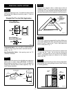
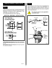
VERTICAL DIMENSION FROM THE FLOOR OF THE UNIT
TO THE CENTRE OF THE HORIZONTAL VENT PIPE
Fig. 23
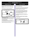
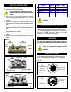
HOW TO USE THE VENT GRAPH
1. Determine the height of the centre of the horizontal
vent pipe exiting through the outer wall. Using this
dimension on the Sidewall Vent Graph (Fig. 21),
locate the point it intersects with the slanted graph
line.
2. From the point of this intersection, draw a vertical
line to the bottom of the graph.
3. Select the indicated dimension, and position the
fireplace in accordance with same.
EXAMPLE A:
If the vertical dimension from the floor of the unit is 11
feet (3352mm) the horizontal run to the face of the outer
wall must not exceed 14 feet (4267mm).
EXAMPLE B:
If the vertical dimension from the floor of the unit is 7 feet
(2133mm), the horizontal run to the face of the outer wall
must not exceed 8-1/2 feet (2590mm).
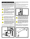
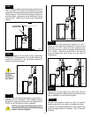
VERTICAL SIDEWALL VENTING GRAPH
(Dimensions in Feet)
Fig. 22
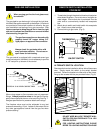
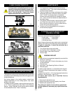
The maximum number of elbow degrees in a system is
270
o
. (This does not include transition elbow from rear
vent to vertical vent.) Fig. 22.
Sample: 1 - 90
o
(Fig. 20) 2 - 45
o
3 - 45
o
4 - 90
o
Total - 270
o