


- 11 -
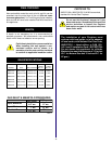
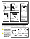
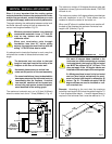
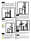
Measure wall thickness and cut adjustable zero clearance
sleeve parts to proper length (MAXIMUM 12"/305mm).
Adjust sleeve to maximum (10-3/8 x 9-3/8). and attach to
firestop with #8 sheet metal screws (supplied). (Fig. 16)
Install firestop assembly.
#8
SCREWS(2)
ADJUSTABLE ZERO
CLEARANCE SLEEVE
ADJUSTABLE
ZERO CLEARANCE
SLEEVE
#8
SCREWS(2)
#8
SCREWS(2)
Maximum Length
12" (294mm)
FIRESTOP
Fig. 15
STEP 2
Fig. 16
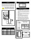
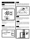
Combustible Walls. Cut a 10-3/8"H x 9-3/8"W (265mm
x 240mm) hole through the exterior wall and frame as
shown. Fig. 15.
Non-Combustible Walls: Hole opening must be 7.5"
(190mm) in diameter.
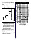
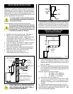
REAR WALL INSTALLATIONS
STEP 1
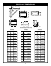
Locate vent opening on wall. To locate hole centre consult
with appropriate fireplace dimensions, page 4. Frame as
shown below.
(240mm)
9-
3/8
"
10-
3/8
"
(255mm)
7-
1/2
"
(190mm)
Vent Opening —
Noncombustible Wall
(framing detail)
Vent Opening —
Combustible Wall
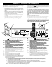
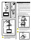
STEP 4
Slip 4" and 7" pipes onto respective flue collars. Make sure
to fix to the fireplace collar the 4" pipe with three (3) screws
before fixing the 7" pipe on the 7" collar. Both pipes must
be on a level plane. Fig. 17.
STEP 3
Measure from fireplace collar or elbow face to face of
outside wall (add 2" for vent pipe overlap. Mark pipes and
cut to length. It is very important that the two pipes are flush
with the outside wall once the fireplace is in its final location.
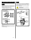
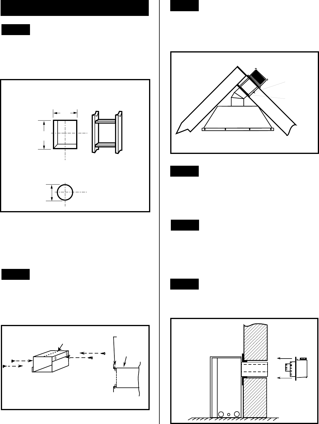
STEP 5
Guide the vent termination 4" collar into the 4" pipe then the
7" collar into the 7" pipe. Do not force the venting into
position. If the pipes do not line up with the termination
collars, disassemble pipes and reattach to the fireplace
collar. (Fig. 18)
STEP 6
Secure fireplace to floor through floor holes and adjustable
frame drywall strip (nailing flange) to frame. (See Framing
& Finishing Section)
Fig. 18
Straight Out Thru the Wall Application
FINISHED
WALL
VENT
TERMINATION
FIRESTOP
ZERO
CLEARANCE
SLEEVE
Fig. 17