


13
Ve r m o n t
®
LIGHT FIXTURE INSTALLATION
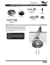
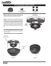
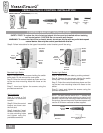
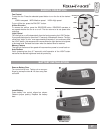
Light Kit
Lightbulb Shield
Socket Plate
Glass Shade
Pack E
Switch Housing Plate
Screws (3)
Pack E
Socket Plate
Screws (3)
Halogen Lightbulb
LIGHT FIXTURE HARDWARE (not to scale)
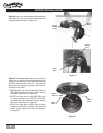
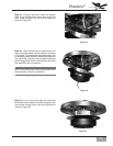
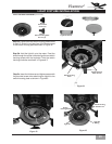
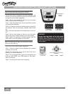
Step 5c. Insert the third screw and tighten screws with
the provided screw driver attaching the light kit to the
switch housing plate as shown in Figure #3.
Step 5a.
Locate the three switch housing plate screws
in pack E. Screw in part way two of the three screws
in the switch housing plate as shown in Figure #1.
Switch Housing
Plate
Switch Housing
Plate Screws
Figure #1
Figure #2
Switch
Housing Plate
Switch Housing
Plate Screws
Light Kit
Light Kit
Wiring
Figure #3
Step 5b. Hold the light kit up to the motor. Feed the
wires through the center hole and align the two switch
housing screws with the keyholes. Twist the switch
housing clockwise as shown in Figures # 2.