


9
BFC36 Balance Flue Heat-Circulating Fireplace
7412647
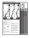
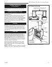
Offset Installation
In order to clear an obstruction, it may be necessary to
offset chimney from vertical. This is accomplished by
using elbows. Use the 30° Offset Elbow table on Page
5 to determine proper offset and parts required.
Each offset requires two (2) elbows. The second elbow
is equipped with support straps. It is very important to
install the second elbow in each offset as close to the
ceiling or support as possible so that the elbow straps
can be secured to framing members to help support the
weight of the chimney.
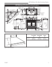
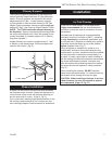
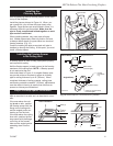
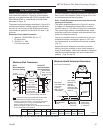
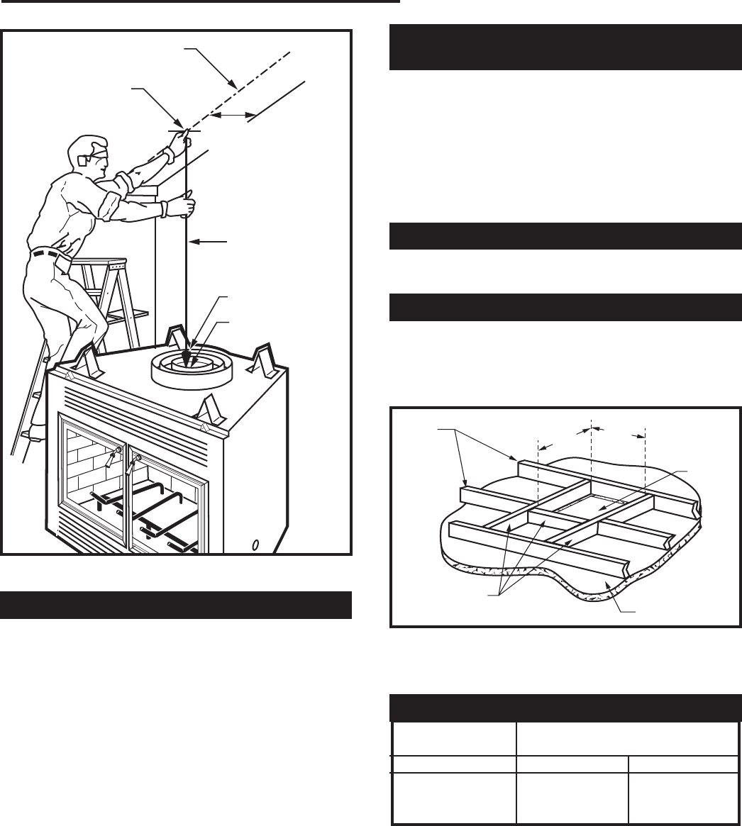
Determine offset distance of your chimney arrangement
from centerline of fireplace to centerline of chimney
where it is to pass through ceiling.
Locate center point of the chimney on ceiling as though
a straight up chimney arrangement is to be used. Mea-
sure your offset dimension from straight up chimney
center point on ceiling.
Ceiling Chimney Hole/
Possible Obstructions
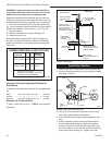
The size of the hole in ceiling will vary with the angle at
which the chimney passes through ceiling.
Drive a nail up through ceiling at marked chimney cen-
ter point. Go to floor above and see where hole will be
cut. Check to see where existing ceiling joists and other
possible obstructions are located...i.e. wiring, plumbing
etc... If necessary, re-position chimney and/or fireplace
to avoid obstructions.
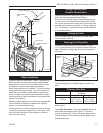
Cutting the Hole
Cover fireplace collar opening and cut proper sized
chimney hole in chimney.
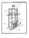
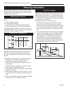
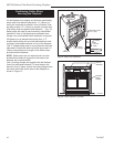
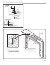
Framing the Ceiling Hole
Frame the ceiling chimney hole as shown in Figure
10. It is good practice to use framing lumber that is the
same size as the ceiling joists; this is a requirement at
attic level.
The inside dimension of the frame must be the same
as the hole size selected from Figure 11 in order to
provide required the 2” (51mm) air space between the
outside diameter of the chimney and the edges of the
framed ceiling hole.
FPC556a
BFC36
LOCATE CENTER LINE
Circulating model
8/21/00 djt
8"
(222mm)
Chimney Centerline
Actual Center-
point
Plumb Line
Plumb Bob
Imaginary Center-
point
FPC556a
Fig. 9 Locate centerline of chimney with plumb line.
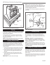
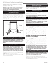
The following table gives firestop spacer model num-
bers:
Chimney Hole Size
Angle of Chimney
at Ceiling
Size of Chimney Vertical 30°
FS2A FS6A
8” Flue 17¹⁄₂” x 17¹⁄₂” 17⁷⁄₈” x 29⁵⁄₈”
(445 x 445mm) (454 x 753mm)
New
Framing
Members
Existing
Ceiling
Joists
Fig. 10 Typical frame for ceiling chimney hole.
FP551b
17 1/2"
Framing chimney hole
5/13/99 djt
Ceiling
Chimney
Hole
17¹⁄₂”
(445mm)
17¹⁄₂”
(445mm)
FP551b
Fig. 11 Ceiling chimney hole sizes necessary for installing
firestop spacer.