


16
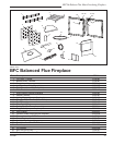
BFC36 Balance Flue Heat-Circulating Fireplace
7412647
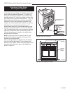
WARNING: Hearth extension must be installed in
accordance with Figure 23 and must not cover the
bottom front opening of the circulating model.
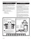
Alternate noncombustible materials may be used pro-
viding the (total) thermal resistance (Rt value) of the al-
ternate material employed is greater than or equal to R
= 1.09 Thermal resistance (R) or thermal conductivity
(K), may be obtained from manufacturer of the material.
Factors are related by the formula K = 1/R. (Fig. 24)
T = given thickness
R = thermal resistance for a given thickness (T)
K = thermal conductivity
Noncombustible material with a lower R value may
be used, provided thickness of material is sufficiently
greater to maintain an equivalent (total) thermal resis-
tance (Rt).
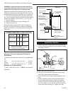
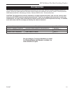
COMMON MATERIALS AND FACTORS
MATERIAL K*
R
MINIMUM
THICKNESS
EH2416
Common Brick
0.458
5.0
1.09 0.50 in.**
0.10 5.46 in.**
(CFM Corporation)
R Value is for 1/2 inch.
* Units of K = BTU/SQ FT/HR/˚F/IN
** Thickness of Listed Material
FP533ADD
Addendum
6/1/99 djt
8/4/99 changed .2 to .1
one inch to 1/2 inch djt
FP533ADD
Fig. 22 Hearth extension material factors.
Example of Determining Hearth Extension
Equivalents
To determine the thickness required for any new mate-
rial:
NEW K of new material (per inch) thickness
required = --------------------------------------- X of listed
thickness K of listed material (per inch) material
Example for Common Brick
T (new) = 5.0/0.458 x 0.50 in. = 5.46 in. (new required
thickness).
FP550
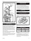
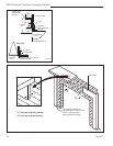
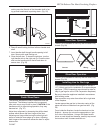
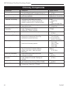
BR/BC - SEALING
DETAILS
9/29/97
Wall Covering
Noncombustible
Decorative Fac-
ing
Seal all cracks
between fireplace
surround and wall
materials with non-
combustible material.
Noncombus-
tible Decorative
Covering
Hearth Exten-
sion Insulation
2 x 4” Header
- Do not notch at
standoffs
Seal crack between
fireplace and hearth
extension with noncom-
bustible material
Safety Strips -
Must be overlapped 1/2”
minimum
Side View
FP550
Fig. 23 Sealing gaps.
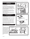
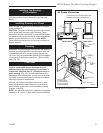
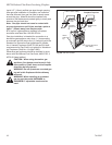
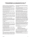
Install Door Handles
1. Remove the door handle stubs from the plastic bag.
2. Remove the large locking nut from right door handle
stub shaft. (Fig. 24)
FP1595
Door Pawl parts
11/05
Pawl
Handle
Shaft
Washer
Large
Locking
Nut
Spacer
Handle
Stub
FP1595
Fig. 24 Right door handle stub parts.
Set
Screw
3. Using 1/8” Allen wrench loosen the set screw and
remove the pawl, spacer and washer.
4. Insert handle shaft through handle opening in right
door.
5. With the handle pointing down and the flat side of
the threaded shaft facing up, replace the washer,
spacer and pawl. Be sure the door adjustment por-
tion of the pawl is on the left side of the handle stub.
Secure with large locking nut. Tighten set screw