


8
BFC36 Balance Flue Heat-Circulating Fireplace
7412647
FPC555a
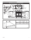
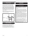
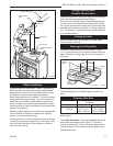
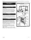
Platform insulation
BFC model
8/21/00 djt
Hard Flat
Surface
Insulation
Platform
FPC555a
Fig. 7 Insulating between platform and fireplace.
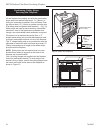
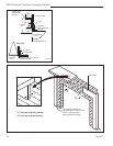
Framing
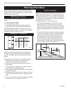
Framing can be constructed before or after the fireplace
is set in place, however, most installers build the frame
before setting the fireplace.
Frame fireplace with 2 x 4 lumber or heavier materi
-
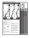
als. Refer to framing dimensions in Figure 1 for basic
fireplace specifications.
NOTE: Framing should be positioned to accommodate
wall covering and fireplace facing material.
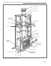
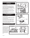
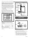
Installing Electrical Wire
The fan requires 120VAC, 60 Hz power which may be
connected to the right side of the fireplace using the
romex pigtail provided with teh unit. This power must
be completed before the fireplace is secured and finish
material applied.
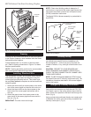
1. Attach the white wire from house power to the white
wire of the romex pigtail and secure with a wire nut.
2. Attach the black wire from the house power to the
black wire of the romex pigtail and secure with a
wire nut.
3. Attach the ground wire from house power to the
ground wire of the romex pigtail and secure with a
wire nut. (Fig. 8)
IMPORTANT: The wire nuts must be tight.
NOTE: Check local building codes to determine if
junction box is required at the romex pigtail/house wire
connection Also check junction box and speed control
(SCVS) installation instructions.
The Model FKSX-A blower assembly is preinstalled in
the BFC36.
FP1062
romex pigtail
8/21/00 djt
Romex Pigtail
(Provided)
Fireplace Electrical
Coverplate
Wire Nuts
(Not pro-
vided)
Ground
Black
White
House
Wiring
(120V
60Hz)
FP1062
Fig. 8 Wiring diagram.
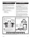
Chimney Set-up
Since you have already preplanned the chimney run,
you should know exactly how the installation is to
be accomplished — how much pipe is required, the
number of elbows, if any, and type of termination to be
used.
CAUTION: REPORT TO YOUR DEALERS ANY
PARTS DAMAGED IN SHIPMENT, SPECIFICALLY
CHECK THE END CONNECTION OF CHIMNEY SEC-
TIONS AND ELBOWS.
NOTE: The BFC36 fireplace must use CFM Corpora-
tion Model triple wall 8” chimney components only. The
installation procedure described in this manual applies
only to this system.
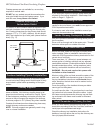
Straight-Up Chimney Installation
To mark the centerline of the flue, put the fireplace in
final position and measure out from the wall: 8³⁄₄" (222
mm). Mark a spot on the ceiling directly above the fire-
place. Draw a line parallel to the back wall through this
mark. (Fig. 9)
Using a plumb bob positioned directly over center point
of fireplace flue collar, mark the ceiling to establish the
chimney center point. (Fig. 9)