


18
BFC36 Balance Flue Heat-Circulating Fireplace
7412647
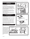
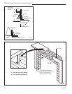
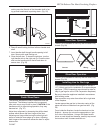
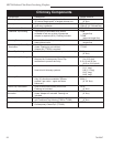
Install 1/2” (13mm) certified gas pipe through opening.
After gas pipe installation is complete, use insulation
that was removed from gas line tube to repack space
around the pipe. Material should be inserted from
outside of the fireplace and packed tightly to totally seal
between the pipe and tube.
Note: Gas pipe should not come in contact with
any wood structures until it has reached a point at
least 1” (25mm) away from fireplace side.
BTU input of a gas appliance installed in fireplace
should be rated less than 100,000 BTU/Hr.
Gas pipe installation is intended for connection to a
decorative gas appliance only when (1.) incorporating
an automatic shutoff device and (2.) complying with the
Standard for Decorative Gas Appliances for Installa-
tion in Vented Fireplaces (ANSI Z21.60) or CSA draft
requirements for Gas-Fired Log Lighters for Woodburn-
ing Fireplaces (Draft No. 4, August 1993).
Decorative gas appliance should be installed in accor-
dance with the National Fuel Gas Code, ANSI Z223.1/
NFPA 54 (latest edition).
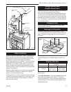
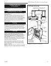
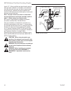
CAUTION: When using decorative gas
appliance, flue damper must be set in fully
open position. Glass doors on the fireplace
must also be fully opened.
WARNING: Do not operate an unvented gas
log set in this fireplace with the chimney
removed.
WARNING: When installing an unvented
gas log set, the model AH3244BK or
AH3244PB 4” adjustable hood must be
used.
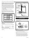
1"
Min.
FP560a
BFC
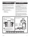
Gas line knockout
8/00
1/2"
Hole in Outer Casing
Gas Line
Tube
Ceramic
Knockout
Supply
Line
Repack Insu-
lation
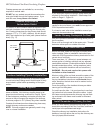
Hole in
Outer Cas-
ing
Ceramic Knockout
(both sides)
FP560a
Fig. 29 Gas line access.
Fireplace Top View