


3
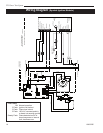
DV Power Vent System
10003262
• This DV Power Vent System was designed to be
used only on units with electronic ignition (EN or EP).
• This DV Power Vent System was certified by CSA
to be used only with CFM Corporation Direct Vent
models, as listed in this manual.
• This DV Power Vent System can be used with any
CFM Corporation side wall vent termination kits,
vertical vent termination kits or snorkel kits (rear vent
termination not to be used).
• This DV Power Vent System must be installed by a
qualified professional according to these instructions.
• Plan the venting layout before starting the installa-
tion.
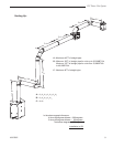
• Maximum TOTAL allowable system length is 40FT
of straight pipe, plus up to five 90 degree elbows.
Any combination of 45 and 90 degree elbows up to a
maximum of 450 degrees is allowed. It is NOT per-
missible to substitute elbows for length of horizontal
or vertical straight pipe.
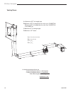
• Can be vented down to a maximum of 12FT, meas-
ured from the center line of the highest section to the
centre line of the lowest section between the fireplace
and the DV Power Vent box.
• Minimum vent length of straight pipe between fire-
place and the DV Power Vent box is:
10 feet for units with input up to 33,000BTU/h;
15 feet for units with inputs from 33,000BTU/h
to 40,000BTU/h.
• Maximum vent length of straight pipe between the
DV Power Vent System box and the vent termination
is 6 FT.
General Information and Instructions for
the DV-Power Vent System Model 7PDVS
• Only vent components manufactured by CFM Corpo-
ration are approved for use with this DV Power Vent
System.
• All 4” and 7” venting connections (twist-lock or
crimped ends) to be sealed with high temperature
silicone.
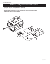
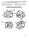
• The 4” and 7” pipes connected to the inlet side of the
DV Power Vent System box to be fitted inside the 4”
pipe and the 7” collar.
• Leave a permanent access for inspection and service
of the DV Power Vent System box.
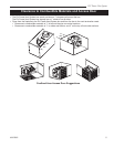
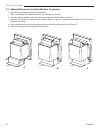
• Confined area definition: when the distance of the
four walls around the sides of the Power Vent Box to
the stand-offs is 3” or less in average.
• When the DV Power Vent box is installed in a con-
fined area, the access door needs to have a mini-
mum size of 12” X 12” and it must be ventilated with
a minimum of 10% open area. In a confined area
installation a minimum distance of 12” (1FT), needs
to be left between the Power Vent Box and the fifth
wall. (Refer to Figures on Page 5).
• When the DV Power Vent box is installed in an un-
confined area, the access door doesn’t need to be
ventilated.
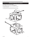
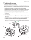
• The power vent motor shaft MUST ALWAYS BE ori-
ented horizontally for proper operation.
• The pressure switch diaphragm MUST ALWAYS BE,
in a vertical position and the hose connection point-
ing down, NEVER up.
• Disconnect power supply when installing or servicing
the fireplace or the power vent system.