


11
DV Power Vent System
10003262
3- DV Power Vent System Setup:
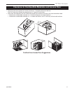
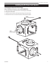
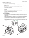
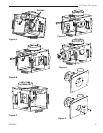
3.1 - Checking the Pressure Switch Position:
The pressure switch diaphragm must be in a vertical plane.
The pressure switch hose connections should NEVER point up. The BEST position is pointing down, but can
be pointed to the sides.
Depending on the final location of the DV Power Vent System box, the pressure switch hose connection needs
to be checked. If the hose connection position needs to be adjusted, follow these steps:
1. Check the pressure switch location;
2. If the hose connection is pointing down, you do not need to change the pressure switch position;
3. If the hose connection location needs to be adjusted, remove the two screws holding the pressure switch to
the bracket.
4. Rotate the pressure switch clockwise or counterclockwise (whichever is better to reach the new position);
5. Re-attach the pressure switch to the bracket with the same screws removed in Step 4.
6. Check all wire connections according to the wiring diagram.
7. Check hose connections between the pressure switch and the blower. Make sure the hose is not kinked.
(Refer to Figure A)
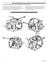
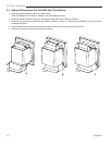
3.2 - Wire Connections:
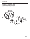
• Remove one screw and one nut that are holding the circuit board cover in place. (Refer to Figure B) Bring
the cover, with the circuit board, the power cord and all the existing wires attached to it, to a rest position.
(Refer to Figure C)
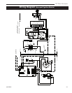
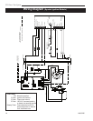
• Make all connections between the DV Power System box and the unit according to the wiring diagram. Use
18 gauge AWS wire with minimum 2/64” insulation.
• For connections to the circuit board, use 3/16” Quick Connect female spade terminals, all others are
screwed connections.
• The DV Power Vent System can be hard wired. To hard wire the DV Power Vent System, disconnect the
power cord from the circuit board and replace it with hard wiring according to the connections shown in the
wiring diagram.
Screw
Nut
Figure A
Figure B
Figure C