


13
Vermont Castings UVS27 Vent-Free Gas Heater
20005004
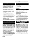
90¡
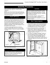
Left Burner Leg
Injector Orifices
ST353a
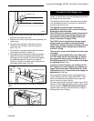
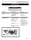
Fig. 20 Be sure injector orifices remain at 90° to the base.
shoulders are inside the burner.
5. Replace rear, left and right log bracket assembly and
replace logs.
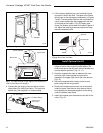
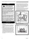
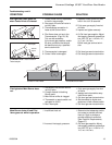
6. Shoulder bolts provided in catalyst kit must be
installed on top of firebox. Use nut to secure in
place. (Fig. 21)
7. Set catalyst on top plate. Secure with two screws
and washers as shown in Figure 21.
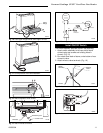
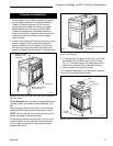
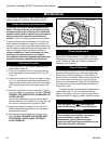
8. Install glass frame assembly by resting the bottom
edge of the frame on support brackets below the
front opening of the firebox. Rotate the top edge of
the assembly toward the firebox, and center it.
Fasten by “rotating” the cams over the top left and
right edges of the frame. (Fig. 22)
ST711
Fig. 22 Rotate cams into place to hold glass frame assembly
in place.
Shoulder
Bolts
ST709
Fig. 21 Install shoulder bolts and set catalytic combustor in
place.
Catalytic Combustor
Apply nut
and
washer to
underside
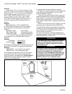
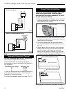
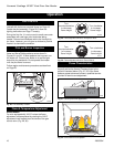
Connect the Gas Supply Line
Check the Rating Plate attached by a steel cable to the
firebox, to confirm that you have the appropriate firebox
for the type of fuel to be used.
The appliance should have a main gas valve provided
in an accessible location for turning on or shutting off
the gas to the main burner.
This appliance should only be connected by a
qualified gas technician. Test to confirm manifold
pressures as specified below.
The UVS27 and its individual shutoff valve must be
disconnected from the gas supply piping during
any pressure testing of that system at test pres-
sures in excess of 1/2 psig (3.5 kPa).
The UVS27 must be isolated from the gas supply
piping system by closing its individual manual
shutoff valve during any pressure testing of the gas
supply piping system at test pressure equal to or
less than 1/2 psig.
There must be a gas shutoff between the stove and
the supply.
In order to connect Natural Gas, use a fitting with
3/8” NPT nipple on the valve side and 1/2” natural
gas supply line with an input of 28,000 BTUs at a
manifold pressure of 3.5” and minimum inlet supply
for adjustment of 5.5” w.c.
In order to connect Propane, use a fitting with 3/8”
NPT nipple on the valve side and 1/2” propane gas
supply line with an input of 28,000 BTUs at a mani-
fold pressure of 11.0” and minimum inlet supply for
adjustment of 11.0” w.c.
Gas connection should be made in accordance with
current National Fuel Gas Code, ANSI Z223.1. Since
some municipalities have additional local codes, be
sure to consult you local authority.
Connect the gas supply and test for leaks. Use a 50/50
solution of liquid soap and water to test for leaks at gas
fittings and joints.
NEVER test with an open flame.
Light the pilot according to the directions on Psage 17,
before going to the next step.