


10
Vermont Castings UVS27 Vent-Free Gas Heater
20005004
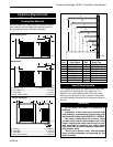
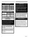
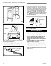
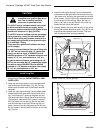
Screw & Washer
Support Shelf
Back Panel
Side
Plate
ST106
Fig. 7 The sides must be at right angles to the back panel in
order for the firebox to fit properly.
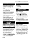
ST125
Firebox washer align
10/15/99 djt
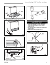
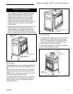
Steel Tab
Side Plate
ST125
Fig. 9 Install the firebox assembly,. Be sure steel tabs
engage ribs on base of firebox.
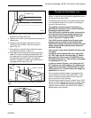
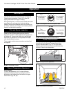
Install Optional Fan Kit
1. Attach the fan to the firebox by engaging the upper
flange of the fan skirt under the lower edge of the
shroud and secure the skirt with the four screws and
one star washer provided. (Fig. 10, 11)
2. Feed the snapstat wire lead up between the inner
and outer rear shroud panels and secure the
snapstat to the upper right side of the inner shroud.
(Fig. 12)
3. Secure the snapstat wire harness to the shroud
panel using the wire tie provided.
4. Route the rheostat control switch and wire forward
under the stove. Use the wire tie to secure the fan
and rheostat wire harnesses together to the tubing
under the bottom heat shield.
5. Install the rheostat onto the bracket to the left of the
valve. (Fig. 13)
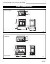
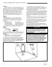
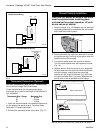
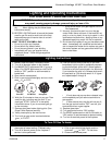
ST105
Shell assy
4/15/99 djt
Wingbolt
Right
Side
ST105
Fig. Secure right side to the back panel.
4. Connect the gas supply line to the burner control
valve before you install the firebox. This may be a
flexible line, (not supplied), or hard plumbing.
1/2” Gas Supply
1/2” NPT x 1/2” Flare Shutoff
Valve
3/8” Flex Line
(from Valve)
FP297a
Fig. 8 Typical gas supply installation.
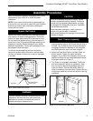
5. Lift the firebox assembly as a unit and slide it back
to position it within the shell. The base of the firebox
should rest on the side support shelves as in Figures
7 and 9. The side plates interlock with the firebox by
use of a pair of steel tabs that engage with the ribs
on the base of the firebox. (Fig. 9) Properly posi-
tioned, the firebox will be level and locked in place. If
not, adjust the levelling screws as required to keep
the entire assembly level.