


12
Vermont Castings UVS27 Vent-Free Gas Heater
20005004
Glass & Catalyst Installation
CAUTION: Air shutter on Natural Gas units
must be adjusted when installing glass
and catalyst for proper operation. LP units
do not use an air shutter.
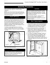
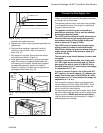
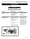
1. Remove screen. (Fig. 18) Remove rear, left and right
log bracket assembly by unfastening the two screws
which hold the burner in place.
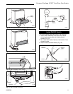
Thermostat Wire / Gauge Maximum Run
18 40 feet
20 25 feet
22 16 feet
Thermostat Connection (Optional)
Use only a thermostat rated for 500 - 750 millivolts.
Do not use low voltage (24V) thermostats.
Check the table below for the appropriate gauge
thermostat wire to use for the length of lead required in
your installation.
1. Install the wall thermostat in the desired location and
run the wires to the stove location. Terminate these
leads with 1/4” female connectors.
2. Connect the thermostat wires to the valve. (Fig. 17)
2. Hold the burner at the right hand side and lift to clear
the right burner leg. Then pull to the right to clear the
injectors on the left hand side.
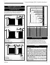
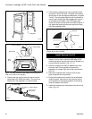
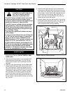
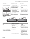
3. Turn burner upside down and remove air shutter.
Turn air shutter upside down and replace on burner.
(Fig. 19)
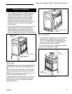
4. Replace burner. Slide the burner in at an angle with
left side lower than the right side. Slide the left side
onto the injectors, making sure the burner leg
remains at a 90° angle to the base. (Fig. 20) Lower
the right hand side down in to place. Make sure the
burner is as far left as possible and the injector
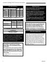
OFF
ON
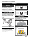
Therm
opile
Black
Black
TP/TH
TP
TH
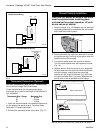
On/Off Switch Wiring
Optional Thermostat/Remote Wiring
ST124b
ST124c
Fig. 17 ON/OFF switch and optional Thermostat/Remote
wiring.
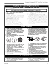
Thermostat/Remote
(Optional)
Therm
opile
Black
Black
TP/TH
TP
TH
ST713
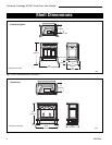
Fig. 18 Remove screen.
Screen Hooks
Air Shutter as Shipped from Factory
Bottom of Burner Pan
ST667
Fig. 19 Remove air shutter, turn upside down and replace.
Air Shutter Turned Upside Down