


66
Vermont Castings Jefferson Direct Vent/Natural Vent Gas Heater
20002191
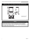
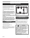
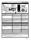
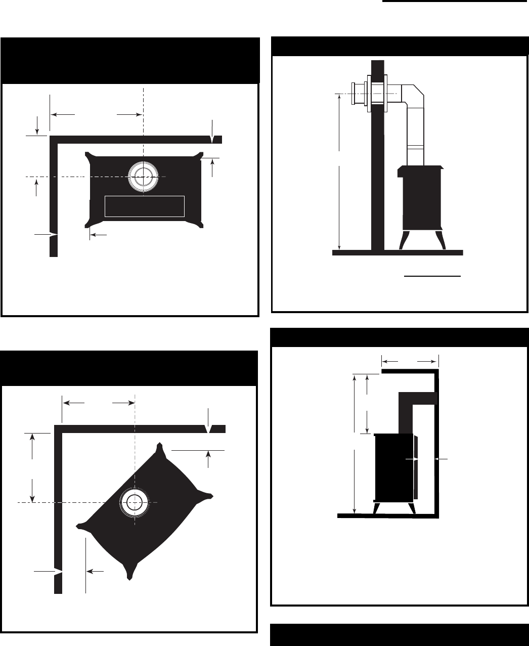
Parallel Installation:
Minimum Clearance and Flue Centerline,
Direct Vent and Natural Vent
C
L
C
L
B
D
C
A
Stove Clearances A: 4” (102mm)
B: 4” (102mm)
Pipe Centerlines C: 14¹⁄₂” (369mm)
D: 9” (229mm)
ST128a
Fig. 3 Parallel installation, minimum back and side clearances,
and flue centerlines.
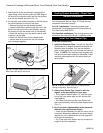
Hearth Requirements
The Jefferson Heater must be installed on rigid flooring.
When the heater is installed directly on any combustible
surface other than wood flooring, a metal or wood panel
extending the full width and depth of the unit must be
used as the hearth. There are no other hearth require-
ments.
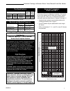
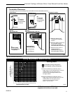
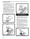
A
Wall Thimble Centerline from Floor
A
Effective Minimum
Wall Thimble 58 ¹/₄” (1480mm)(CFM Majestic Pipe)
Centerline 54¹⁄₄” (1378mm) (Simpson DuraVent Pipe)
ST131a
Fig. 5 Minimum wall thimble centerline.
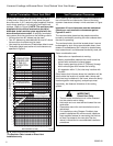
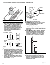
Direct Vent Only
Wall and Ceiling Clearances
*
needed for installing DuraVent Minimum Vent Kit #2792 or
CFM/Majestic Minimum Vent Kit #7TFSDVSK.
A
C
D
B
A: Rear Wall 4” (102mm)
B: Min. Clearance 43¹⁄₂” (1105mm)*
C: Min. Alcove Height 72” (1830mm)*
D: Max. Alcove Depth 48” (1220mm)
Sidewall Clearance 4” (102mm)
ST101a
Fig. 6 Dimensions and clearances to ceiling or alcove.
Direct Vent Only
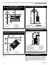
Corner Installation: Minimum Clearance and
Flue Centerline, Direct Vent & Natural Vent
Stove Clearance A: 4” (102mm)
Pipe Centerline B: 14³⁄₄” (375mm)
ST129b
Fig. 4 Corner installation, minimum corner clearances and flue
centerline.
A
A
B
B