


5
Vermont Castings Jefferson Direct Vent/Natural Vent Gas Heater
20002191
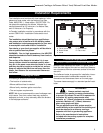
Installation Requirements
The installation must conform with local codes or, in the
absence of local codes, with the National Fuel Gas
Code, ANSI Z223.1 - latest edition. (EXCEPTION: Do
not derate this appliance for altitude. Maintain the
manifold pressure at 3.5 inches w.c. for Natural Gas,
and 10 inches w.c. for Propane).
In Canada, installation must be in accordance with the
current CSA B-149.1 Installation Codes and/or local
codes.
The installation should be done by a qualified ser-
vice person who is familiar with the building codes
and installation techniques appropriate for your area
to accomplish a safe and effective installation.
Your dealer or your local gas supplier will be able to
refer a qualified service person.
WARNING: Due to high temperatures, the HEATER
should be located out of traffic and away from furniture
and draperies.
The surface of the Heater Is hot when it is in use.
Young children should be watched carefully when
they are in the same room when the Heater is in use,
and they should be taught to avoid the hot surface.
Keep any objects that can burn well away from the
Heater, and observe the recommended clearances
that follow.
Locating the Stove
In choosing a location for the stove, consider:
• The location of outside walls;
• Where additional heat is needed:
• Where family members gather most often;
• The vent system requirements.
NOTE: We do not recommend the use of wallpaper next
to this stove. Over time, radiant heat may cause the
wallpaper to shrink, or may adversely affect the binders
in the wallpaper adhesive.
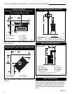
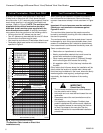
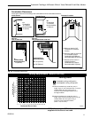
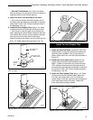
Clearance Requirements
Minimum Clearances to Combustible Materials
Measure side clearances as shown in Figures 3 and 4
from the outer edge of the cast iron stove top. Measure
rear clearances from the outermost surface of the steel
rear skirt.
The Jefferson heater is approved for installation into an
alcove constructed of combustible materials to the
dimensions and clearances shown on the next page.
The same clearances apply in a standard parallel instal-
lation.
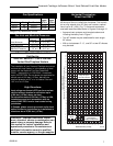
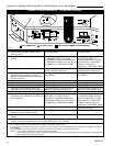
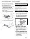
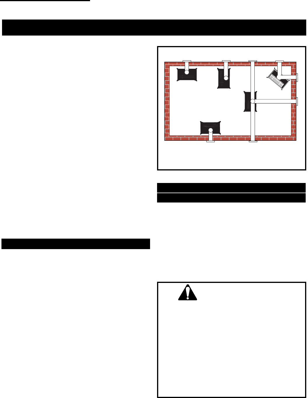
A
B
E
C
D
ST207
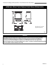
A. Flat on corner wall
B. Room Divider
C. Island
D. Cross Corner
E. Flat on wall
Fig. 2 Possible stove locations.
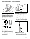
Direct Vent System Only
WARNING:
• Always maintain required
clearances (air spaces) to nearby combustibles
to prevent fire hazard. Do not fill air spaces with
insulation. All venting components must
maintain a 1" (25mm) clearance to combustible
materials. Maintain a 6” (150mm) clearance
when using single wall pipe.
• The gas appliance and vent system must be
vented directly to the outside of the building and
never be attached to a chimney serving a
separate solid fuel or gas-burning appliance.
• Refer to the manufacturer's instructions
included with the venting system for complete
installation procedures.