


19
Vermont Castings Jefferson Direct Vent/Natural Vent Gas Heater
20002191
Venting System Assembly - Natural Vent
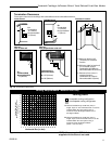
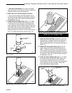
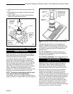
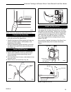
9. Install the storm collar and seal around the joints. (Fig.
31)
10. Add additional vent lengths to achieve the proper
overall height.
11. Apply cement to the inner and outer termination
collars and install the terminal cap.
Storm
Collar
Sealant
Upper edge
of flange
goes under
upper
shingles
Flashing
#7DVSKV
(A, B, or F)
Roof Support
Use three #5
sheet metal
screws at
each joint
ST221
Fig. 31 Roof support and flashing.
General Information
The Jefferson Heater is shipped from the factory as a
Direct Vent Heater. It may be converted to a Natural
Vent heater by installing the Vermont Castings Model
Z31D00 FSDHAG Draft Hood Adapter.
The Jefferson Heater is approved for installation as a
Natural Vent. CFM Direct Vent pipe could be used
directly after the Draft Hood Adapter up to the ceiling,
then B-vent pipe must be used. Do not mix types of B-
vent pipe; use components from one maker or the
other. Follow the vent component maker’s instructions
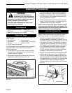
exactly. The heater will also accept standard or
enamelled 7” (150mm) diameter pipe, around the Type
B venting, for decorative purposes only. (Fig. 32)
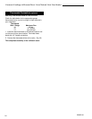
NOTE: The restrictor plate supplied with the stove
is not used for Natural Vent applications.
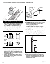
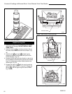
The Jefferson stove, when installed as a Natural vent
heater, includes a vent safety switch. (Fig. 64, Page 33)
Decorative 7”
Pipe
4” B-vent
Pipe
Draft Hood
Adapter
ST358
Fig. 32 Decorative 7” pipe may be fitted around the B-vent
pipe.
CFM Direct Vent
System may be
used after Draft
Hood up to the
ceiling.
Operating the stove when it is not connected to a
properly installed and maintained venting system, or
tampering with or disconnecting the vent safety switch,
can result in carbon monoxide (CO) poisoning and
possible death.
For U.S. installations: The venting system must
conform with local codes and/or the current National
Fuel Gas Code, ANSI Z22.1.
For Canadian installations: The venting system must
conform to the current CSA B149.1 installation code.
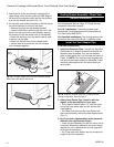
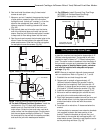
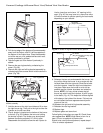
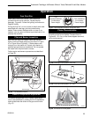
Install the Vent Pipe
Apply a bead of sealant around bottom end of inner
starter pipe (found in bag with logset) and attach to
stove. Apply a bead of sealant around top of inner
starter pipe and install the Z31D00 FSDHAG Draft
Hood according to Draft Hood instructions. (Fig. 33)
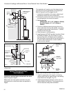
Attach the first section of venting to the draft hood.
Depending on the length of the individual venting
sections and the lengths of the decorative pipe (if
installed), you may need to slip the decorative pipe over
the venting sections before attaching upper sections to
lower ones. The sections of decorative pipe should be
oriented with their seams (if any) toward the wall;
sections usually do not need to be fastened at each
joint, other than slip sections. If the layout includes a
slip section, this should be the last section of pipe
visible in the room, at the ceiling. Complete the venting
according to the vent maker’s instructions.