


1414
Vermont Castings Jefferson Direct Vent/Natural Vent Gas Heater
20002191
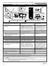
General Information
The Jefferson is approved for installation only with the
vent components listed on Page 12. Follow the vent
component instructions exactly.
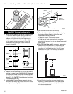
For U.S. installations: The venting system must
conform with local codes and/or the current National
Fuel Gas Code, ANSI Z223.1
For Canadian installations: The venting system must
conform to the current CSA B149.1 installation code.
Install the Vent Adapter Pipe
(CFM Vent Components)
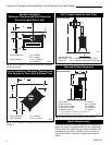
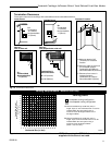
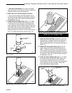
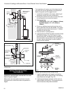
1. Install the Restrictor Plate. Consult the ‘Vent Run
Specifications’ on page 8 to determine whether the
restrictor plate is needed. If so, put the restrictor
plate in place within the inner flue collar as shown in
Figure 16. NOTE: The restrictor plate supplied with
the vertical termination should be discarded. Install
restrictor plate supplied with the stove directly at
stove outlet.
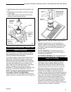
Venting System Assembly - Direct Vent
2. Attach Inner Starter Pipe, (found in with the
logset), to the next section of inner pipe.
• Run a bead of sealant about 1/2” from the upper
end of the Inner starter pipe and join the two sec-
tions together.
• Drill three pilot holes into the Inner Starter and
secure the assembly with three sheet metal screws.
(Fig. 17)
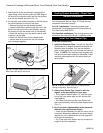
3. Dry fit the Inner pipe assembly to the stove and
determine the required vent length.
• Insert the vent assembly into the flue collar, but do
not attach. Measure to determine the correct length
required for your installation and cut the upper end
of the pipe as necessary.
• Dry fit the outer vent section and cut to match the
height of the Inner assembly.
ST210
Fig. 16 Install the restrictor plate only if required for the
venting configuration. Refer to page 8.
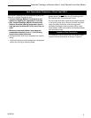
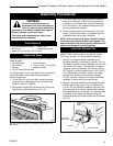
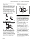
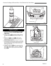
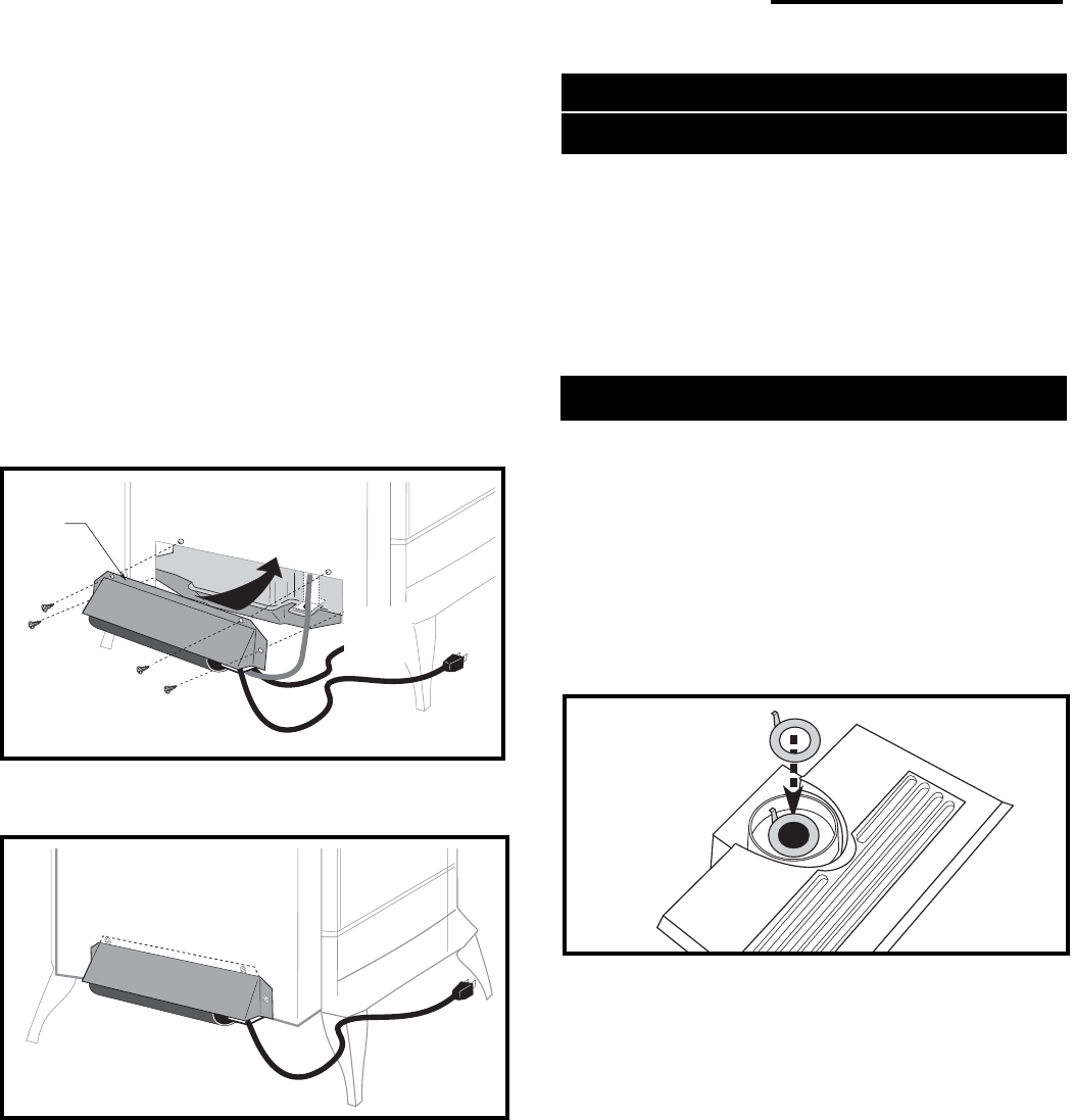
Upper
Flange
ST240
Fig. 19 The upper flange of the fan skirt should be located
behind the lower edge of the shroud.
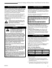
to
Control
Valve
ST241
Fig. 20 Correct position of fan skirt installation.
3. Attach the fan to the rear shroud by engaging the
upper flange of the fan skirt under the lower edge of
the shroud and secure the skirt with the four screws
and one star washer provided. (Fig. 14)
4. The rheostat control switch attaches to the left side of
the valve bracket at the front of the stove.
• Remove the plug from the rheostat bracket.
• Insert the switch box shaft through the hole in the
back of the right side of the valve bracket, aligning
the locator pin with the smaller hole in that bracket.
• Attach the retaining nut to the switch control shaft
to secure it to the plate.
• Attach the Control Knob to the rheostat shaft.
• Use the wire tie to secure the fan and rheostat
wire harnesses together.