


16
Resolute Acclaim Woodburning Stove
2000893
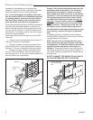
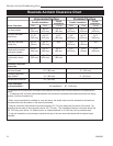
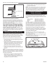
Because of their restricted air flow and heat retention characteristics, specific construction requirements and special
clearances apply to installations into alcoves. No stove or chimney connector heat shields are used in alcove installa-
tions. Bottom heat shield requirements remain the same as for other installations.
ALCOVE INSTALLATION OF THE RESOLUTE ACCLAIM IS NOT PERMITTED IN CANADA.
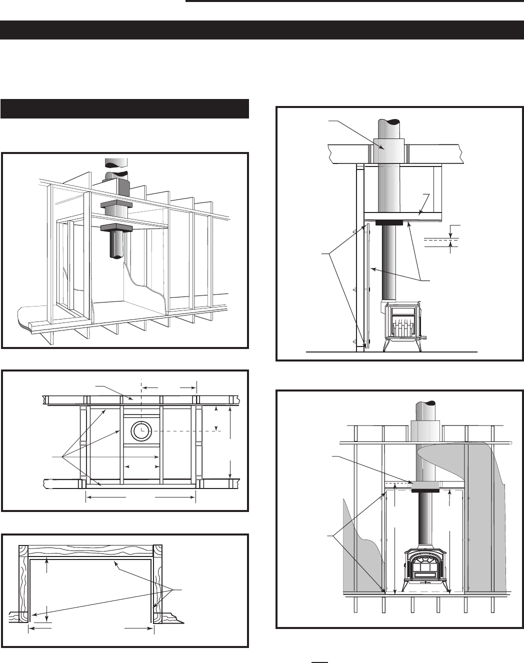
Alcove Installations
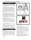
Construction Requirements
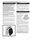
Showing noncombustible ceiling framing and maximum
and minimum permitted dimensions.
St504
Alcove cutaway
11/00
ST504
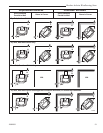
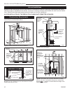
Fig. 22 Cutaway perspective of alcove installation.
24"
14¹⁄₄"
48" Min.
11"
Min.
36"
Min.
ST505
Alcove Ceiling plan
11/00
Existings
Combustible Framing
Metal studs
support 7/16”
Durock© (or
equivalent)
ceiling
ST505
Fig. 23 Reflected ceiling plan.
36"
(914mm)
Max.
48" (1219mm) Min.
ST502
Intrepid
Alcove floor plan
11/10/00 djt
7/16” Durock©
(or equivalent)
spaced 1” off
wood studs on
noncombustible
spacers
Use recommended
floor protection
ST502
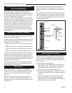
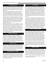
Fig. 24 Floor plan. Sheetrock on front face butts to Durock©
(or equivalent) alcove lining.
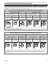
65"
62" Min.
to Alcove
Ceiling
ST610
Alco
ve front view
01/01
Ceiling sup-
port package
extends 2”
below Durock©
(or equivalent)
ceiling
1” air gap,
top, bottom,
on both sides
and back wall
ST610
NOTE: From
62” to 65” must
be covered by
a noncombus-
tible material.
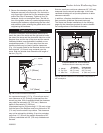
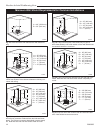
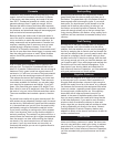
Fig. 26 Front section: 65” minimum clearance to combus-
tibles on front face. Combustible facing may overlap metal
studs by only 1”. It should not extend below the height of the
noncombustible ceiling.
ST609
Alcove side view
01/01 djt
RES OL UT E
Acclaim
Joist Shield
(supplied
by chimney
manufac-
turer)
Metal
Stud
Combustible
facing may
overlap
metal studs
by only 1”
7/16” Durock© (or
equivalent)
1” air gap top
and bottom,
on both sides
and back
wall
ST609
Fig. 25 Alcove side section.