12
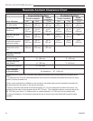
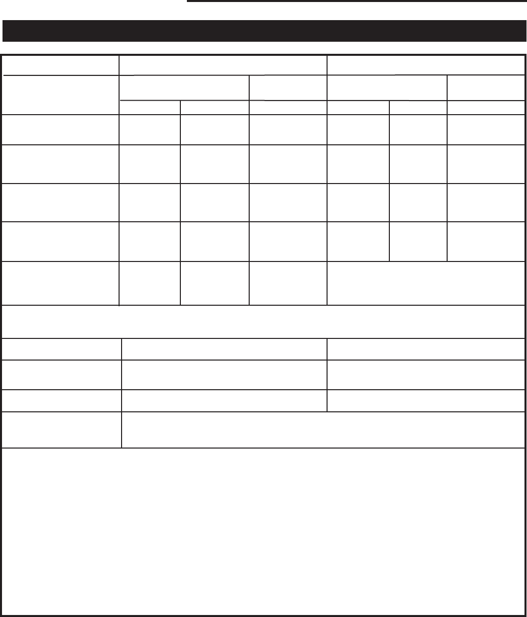
Resolute Acclaim Woodburning Stove
2000893
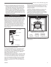
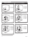
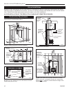
(A) 15” (B) 24” (C) 15” (D) 8” (E) 13” (F) 8”
(380 mm) (610 mm) (380 mm) (203 mm) (330 mm) (203 mm)
(G) 15” (H) 24” (I) 15” (J) 8” (K) 13” (L) 8”
(380 mm) (610 mm) (380 mm) (203 mm) (330 mm) (203 mm)
(M) 15” (N) 10” N/A (O) 8” (P) 7” N/A
(38mm) (254 mm) (203 mm) (180 mm)
(Q) 15” (R) 15” (S) 15” (T) 8” (U) 9” (V) 8”
(380 mm) (380 mm) 380 mm) (203 mm) (23mm) (203 mm)
(Q) 15” (R) 17” (S) 15” *
(380 mm) (432 mm) (380 mm)
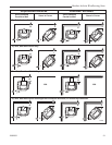
Protected SurfaceUnprotected Surface
Corner
Installation
Corner
Installation
Parallel Installation
Parallel Installation
No heat shields
Stove Clearance
Resolute Acclaim Clearance Chart
* Clearances with double-wall connectors and protected surfaces have not been tested for the Resolute Ac-
claim.
** A distance of 48” must be maintained between the stove and moveable combustible items such as drying
clothes, furniture, firewood, etc.
1
When a rear heat shield is installed on a top exit stove, the shield insert must be attached to the shield so
the area behind the flue collar on the stove is protected.
2
Chimney connector heat shields must extend exactly 28” (710 mm) above the flue collar of the stove. No
shielding can be used on the connector above 28” (710 mm). The unshielded chimney connector above the
28” (710 mm) point will be 14” (360mm) from an unprotected wall or 8” (203 mm) from a protected wall.
3
In top exit installations, this clearance requires the use of the rear stove heat shield with the shield insert
installed.
Side Rear Corner Side Rear Corner
Top exit, rear heat
shield only
1
Rear exit, rear heat
shield only
Top exit, rear h.s.,
single-wall connector,
connector shields
1,2
Top exit, rear h.s.,
double-wall connec-
tor
1,3
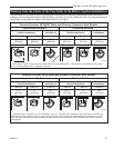
Chimney Connector
Clearance
No Heat Shields 23” (580 mm) 12” (305 mm)
Chimney connector
heat shields
2
14” (360 mm) 8” (203 mm)
Double-wall connector
3
16” (410 mm) *
Front Clearance
to Combustibles** All Installations 48” (1220 mm)


