


9
Dutchwest Natural Vent Gas Heater
30002008
ST671
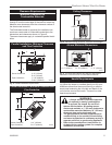
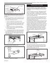
attach snapstat
Snapstat
Left Air Duct
ST671
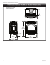
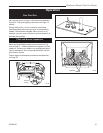
Fig. 12 Install the snapstat and connect the extension wire
terminals. View is with top removed, however, access is
available through the rear when installing fan before gas line
connection.
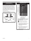
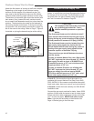
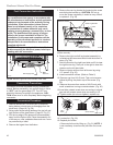
9. After sliding the firebox in place, the rheostat control
switch attaches to the left side of the valve bracket
at the front of the stove. (Fig. 13)
• Remove the plug from the rheostat bracket.
• Insert the switch box shaft through the hole in the
back of the right side of the valve bracket, align-
ing the locator pin with the smaller hole in that
bracket.
• Attach the control knob to the rheostat shaft.
• Use the wire tie to secure the fan and rheostat
wire harnesses together.
10. Plug the power cord into a standard grounded
110 volt household outlet. If the fan control knob is
not turned to the OFF position, the fan will turn on
when the temperature at the snapstat reaches ap-
proximately 109°F.
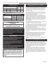
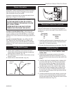
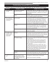
MOTOR
SNAPSTAT
ON/OFF
RHEOSTAT
WHT
WHT
BLK
BLK
BLK
GR
N
BLK
POWER
ST196
FK26 fan diangram
11/99
ST196
Fig. 14 #2767 / FK26 fan wiring diagram.
ST758
Dutchwest
attach rheostat
5/15/03 djt
Retaining Nut
Control Knob
ST758
Fig. 13 Attach rheostat to left side of valve.
Rheostat
Venting System Assembly
The venting collar is on the sheet metal draft hood/heat
exchanger assembly, over the firebox. Use a B-vent
adapter, from the same maker as the rest of the B-vent
components, to join the first section of venting to the
draft hood.
The stove includes a spill switch. Operating this stove
when not connected to a properly installed and main-
tained venting system, or tampering with or disconnect-
ing the spill switch, can result in carbon monoxide (CO)
poisoning and possible death.
The stove includes a bracket for installing decorative 6”
(150mm) round stove pipe around the B-vent, for ap-
pearance purposes only. The decorative pipe need not
be concentric with the vent pipe.
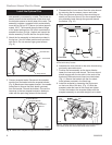
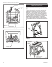
If the installation includes decorative stove pipe around
the venting system, make a cardboard template of the
decorative pipe by tracing its circumference. Put this
template in the flue recess in the stove top. Position the
template to fit well against the front of the recess. (Fig.
16) Use this template to locate the bracket to hold the
decorative pipe. Depending on spacing, the bracket
may fit inside the decorative pipe without interfering
with the vent system. Fasten the bracket to the draft
hood/heat exchanger assembly with a sheet metal
screw.
ST777
Dutchwest
nv
decorative pipe
template
6/20/03 djt
Template
Sheet Metal Screw
Bracket
ST777
Fig. 16 Use a template to locate the bracket for decorative
pipe to surround the B-vent pipe.
Insert the B-vent adapter into the flue collar and drill
1/8” (3mm) pilot holes through both the stove’s collar
and the adapter. Attach the adapter to the flue collar
with sheet metal screws. (Fig. 17)
ST777
Dutchwest
nv
decorative pipe
template
6/20/03 djt
ST778
Fig. 17 Attach the B-vent adapter to the flue.