


15
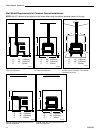
Dutchwest Seneca
2006063
K
L
M
N
N
Q
O
R
P
S
S
T
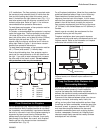
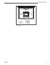
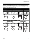
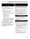
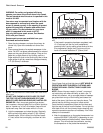
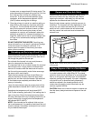
Distance from the Center of the Flue Collar to the Wall in Top Exit Seneca Installations
The information on this page is helpful in planning stove placement for top exiting installations, particularly those
installations with chimneys that pass through the ceiling. However, this is not a clearance chart. For clearance infor-
mation, refer to the clearance chart on Page 12. The terms “Side” and “Rear” refer to the distance from the center of
the flue collar to the respective wall. The term “Front” refers to the distance from the center of the flue collar to the
front edge of the hearth. The asterisk indicates U.S./Canada.
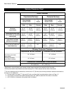
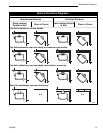
Seneca WITHOUT Stove and Chimney Connector Heat Shields
Unprotected Surfaces Protected Surfaces
Stove Installed Stove Stove Installed Stove
Parallel to Wall inCorner Parallel to Wall in Corner
Side Rear Front Corners Front Side Rear Front Corners Front
(A) (B) (C) (D) (E) (F) (G) (H) (I) (J)
29” 26¹⁄₄” 34” / 36”* 27¹⁄₂” 34” / 36”* 19” 18¹⁄₄” 34” / 36”* 19¹⁄₂” 34” / 36”*
737mm 667mm 915mm 700mm 915mm 483mm 464mm 915mm 495mm 915mm
A
B
C
D
D
G
E
H
F
I
I
J
Seneca WITH Stove and Chimney Connector Heat Shields
Unprotected Surfaces Protected Surfaces
Stove Installed Stove Stove Installed Stove
Parallel to Wall inCorner Parallel to Wall in Corner
Side Rear Front Corners Front Side Rear Front Corners Front
(K) (L) (M) (N) (O) (P) (Q) (R) (S) (T)
29” 28¹⁄₄” 34” / 36”* 19¹⁄₂” 34” / 36”* 19” 15” 34” / 36”* 19¹⁄₂” 34” / 36”*
737mm 464mm 915mm 495mm 915mm 483mm 381mm 915mm 495mm 915mm