


10
Dutchwest Seneca
2006063
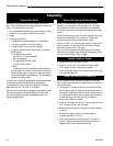
Wall Shields
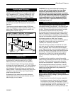
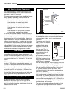
One way to reduce clearances is with a wall shield
constructed of 24 gauge or heavier sheet metal, or of
another noncombustible material such as 1/2" (13 mm)
insulation board such as Durock
®
or Wonderboard
®
, or
common brick “laid on flat,” with the 3¹⁄₂" (90 mm) side
down.
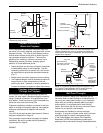
Shields must be spaced out from the combustible
surface 1" (25 mm) on noncombustible spacers, as in
Figure 13. The spacers should not be directly behind
the stove or chimney connector.
Air must be able to flow between the wall and the
shield. At least 50% of the bottom 1" (25 mm) of the
shield must be open, and the shield must be open at
the top. Metal screening across the top will keep small
stray objects from being trapped behind the shield.
(Fig. 13)
Stud Wall
Framing
Wall Shield
Noncombus-
tible Spacers
and Fasteners
Drywall
Air Flow
Air Flow
Screen
Shield
Metal Spacer
ST248
Fig. 13 Approved wall shield construction.
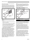
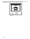
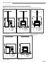
Fireplace and Mantel Trim Shields
A fireplace installation requires special clearance
between the side of the stove and the right and left
walls, between the side of the stove and the decorative
side trim on the fireplace face, and between the top of
the stove and the mantel.
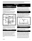
1" (25mm)
1/4" (6mm)
ST501
Fig. 14 A custom-formed
mantel shield.
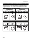
Safe Ways to Reduce Clearances
Your stove has specific clearance requirements that
have been established through careful research and
testing to UL and ULC standards.
Clearance requirements have been established to meet
every installation possibility, and they involve the
combination of basic variables:
• When the stove
has no
listed heat shield
• When the stove
has
a listed heat shield
• When the wall
has no
heat shield
• When the wall
has
a heat shield
• When the stove
has
a double-wall chimney
connector.
• When the stove has a single-wall connector
wit heat shields, or without heat shields.
In general, the greatest clearance is required when you
locate a stove with no heat shield near a wall with no
heat shield. The least clearance is required when both
the stove and the wall have heat shields. Reducing a
stove clearance may require a listed heat shield on the
chimney connector as well, or a double-wall connector.
Clearances may be reduced only by means approved
by the regulatory authority and in accordance with the
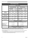
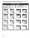
clearances listed in this manual. The charts and sample
installations that follow list all the clearances required
for the various installation configurations of Seneca.
Noncombustible shields installed 1” (25mm) away from
the combustible surface on noncombustible spacers,
called ventilated shields, may be used to reduce
clearances.
To protect a mantel from the
heat of a stove in a fireplace
installation, use a custom-
made ventilated mantel
shield that is at least 48”
(1220mm) long, centered
over the stove. (Fig. 14)
Ventilated shields for side
trim must extend the full
length of the trim.
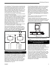
An unprotected mantel (“A”,
Fig. 15) cannot be more than
9” (230mm) deep and must
have a minimum clearance
of 39” (991mm), measured
from the stove’s top plate. With a ventilated shield, this
clearance may be reduced safely to 23” (584mm).
Unprotected top trim (B) protruding 9” (230mm) or less
from the face of the fireplace must be a minimum of
39” (991mm) from the stove’s top surface. With a
ventilated trim shield, this clearance may be reduced
safely to 23” (584mm).
Unprotected side trim (C) that protrudes 2” (50mm) or
less from the face of a fireplace must have a minimum
clearance of 14” (356mm), measured from the stove’s
top side edge. With a ventilated trim shield, the
clearance may be reduced safely to 6” (152mm). If the
trim extends more than 2” (50mm), it is subject to the
requirements for wall clearance.
The charts and sample installations that follow list all
the clearances required for the various installation
configurations of the Seneca.