


7
Vermont Castings Defiant
Accessories to help make the connection between
stainless steel chimney liners and your Defiant are
available through your local dealer.
Chimney Connector Guidelines
A chimney connector is the single-wall pipe that
connects the stove to the chimney. The chimney itself
is the masonry or prefabricated structure that encloses
the flue. Chimney connectors are used only to connect
the stove to the chimney.
Single-wall connectors should be made of 24 gauge
or heavier steel. Do not use galvanized connector; it
cannot withstand the high temperatures that smoke and
exhaust gases can reach, and may release toxic fumes
under high heat. The connector may be 6" (150 mm) or 8
" (200 mm) in diameter.
If possible, do not pass the chimney connector
through a combustible wall or ceiling. If passage
through a combustible wall is unavoidable, refer to the
section on Wall Pass-Throughs. Do not pass the
connector through an attic, a closet or similar con-
cealed space. The whole connector should be ex-
posed and accessible for inspection and cleaning.
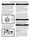
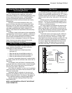
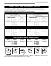
In horizontal runs of chimney connector, maintain a
distance of 24" (610 mm) from the ceiling. Keep it as
short and direct as possible, with no more than two 90
degree turns. Slope horizontal runs of connector
upward 1/4" per foot (20 mm per meter) going from the
stove toward the chimney. The recommended maxi-
mum length of a horizontal run is 3 feet (1 meter), and
the total length of the chimney connector should be no
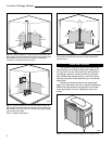
longer than 8 feet (2.5 meters). In cathedral ceiling
installations, extend the prefabricated chimney down-
ward to within 8 feet (2.5 meters) of the stove. This will
help maintain a good draft by keeping the smoke warm,
so that it rises readily.
Wear gloves and protective eyewear when drilling,
cutting or joining sections of chimney connector.
Single-wall Chimney Connectors
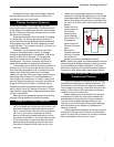
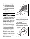
• Begin assembly at the flue collar of the stove. Insert
the first crimped end into the stove’s flue collar, and
keep each crimped end pointing toward the stove.
Fig. 4. Use the holes in the flue collar as guides to
drill 1/8" (3 mm) holes in the bottom of the first
section of chimney connector and secure it to the
flue collar with three #10 x 1/2" sheet metal screws.
Lift off the griddle, and shield the stove's surface
between the griddle opening and the front of the
flue collar to protect the finish when you drill the
front hole.
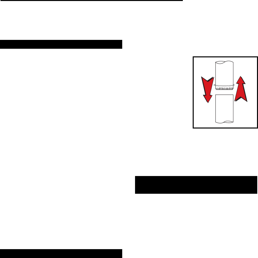
• Fasten each joint between sections of chimney
connector, including telescoping joints, with at least
three sheet metal screws. Holes in the top of each
section of chimney connector serve as guides when
you drill 1/8" (3 mm) holes in the bottom of the next
section.
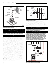
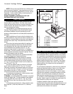
• Fasten the chim-
ney connector to
the chimney.
Instructions for
various installa-
tions follow. Fig. 5
illustrates the
general layout of
chimney connector
parts.
• Be sure the
installed stove and
chimney connector
are correct dis-
tances from nearby combustible materials.
NOTE: Special slip pipes and thimble sleeves that form
telescoping joints between sections of chimney connec-
tor are available to simplify installations. They often
eliminate the need to cut individual connector sections.
Consult your local dealer about these special pieces.
Securing the Single-wall Connector to a
Prefabricated Chimney
Follow the installation instructions of the chimney
manufacturer exactly as you install the chimney. The
manufacturer of the chimney will supply the accesso-
ries to support the chimney, either from the roof of the
house, at the ceiling of the room where the stove is
installed, or from an exterior wall.
Special adaptors are available from the chimney
manufacturer to make the connection between the
prefabricated chimney and the chimney connector.
The top of such adaptors attaches directly to the
chimney or to the chimney’s ceiling support package,
while the bottom of the adaptor is screwed to the
chimney connector.
These adaptors are designed so the top end will fit
outside the inner wall of the chimney, and the bottom
end will fit inside the first section of chimney connector.
When assembled in this way, any soot or
Flue Gas
Direction
Toward
Stove
ST242
Fig. 4 Chimney connector.