


16
Vermont Castings Defiant
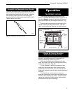
Set Up Your Stove
Cast iron stoves are heavy, and it will take two to
four people to move your Defiant into position.
Wipe the protective coating of oil from the griddle
with a clean dry rag or a paper towel.
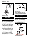
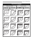
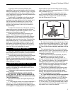
Install the handle on the griddle. Slip the bolt
through a nylon bushing, then through the handle and
the other bushing, then through the steel spacer and
into the griddle tab. (Fig. 16) Tighten securely.
Assembly
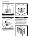
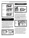
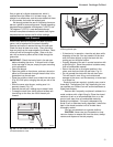
Install the Optional Bottom Heat Shield
NOTE: The Bottom Heat Shield is required in most
installations. Refer to Floor Protection, Page 10, for
further details.
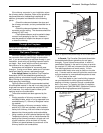
1. Remove the four 10-24 x 1/2" hex head bolts from
the corners of the ash drop on the stove bottom.
2. Screw the four 1¹⁄₄" spacers into the holes from
which you removed the bolts, finger-tight.
3. Align the bottom heat shield against the spacers
with the stepped side toward the rear of the stove.
4. Secure the shield with the four hex head bolts
removed from the stove bottom previously. Tighten
securely. (Fig. 17)
Spacers
ST537
Fig. 17 Attach the optional bottom heat shield.
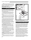
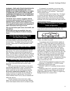
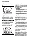
Install the Optional Ash Door Heat Shield
1. Remove the two Phillips pan head screws from the
ash door.
2. Insert the screws through the ash door heat shield
(from the painted side), place the 5/16" spacers
over the screws, and carefully thread them back into
the original holes. (Fig. 18) The curved lip should be
upward, under the ashlip of the stove.
3. Tighten securely.
ST538
Spacers
Fig. 18 Install the ashdoor heat shield.
Adjust the Leg Levellers
Lift the stove slightly so there is no weight on the leg
while making the adjustment.
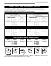
Attach the Damper Handle
Use the 1/4" -20 x 3" screw to attach the damper
handle to the damper stub on the left side. Refer to the
chart on page 35 for hardware sizes.
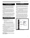
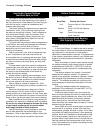
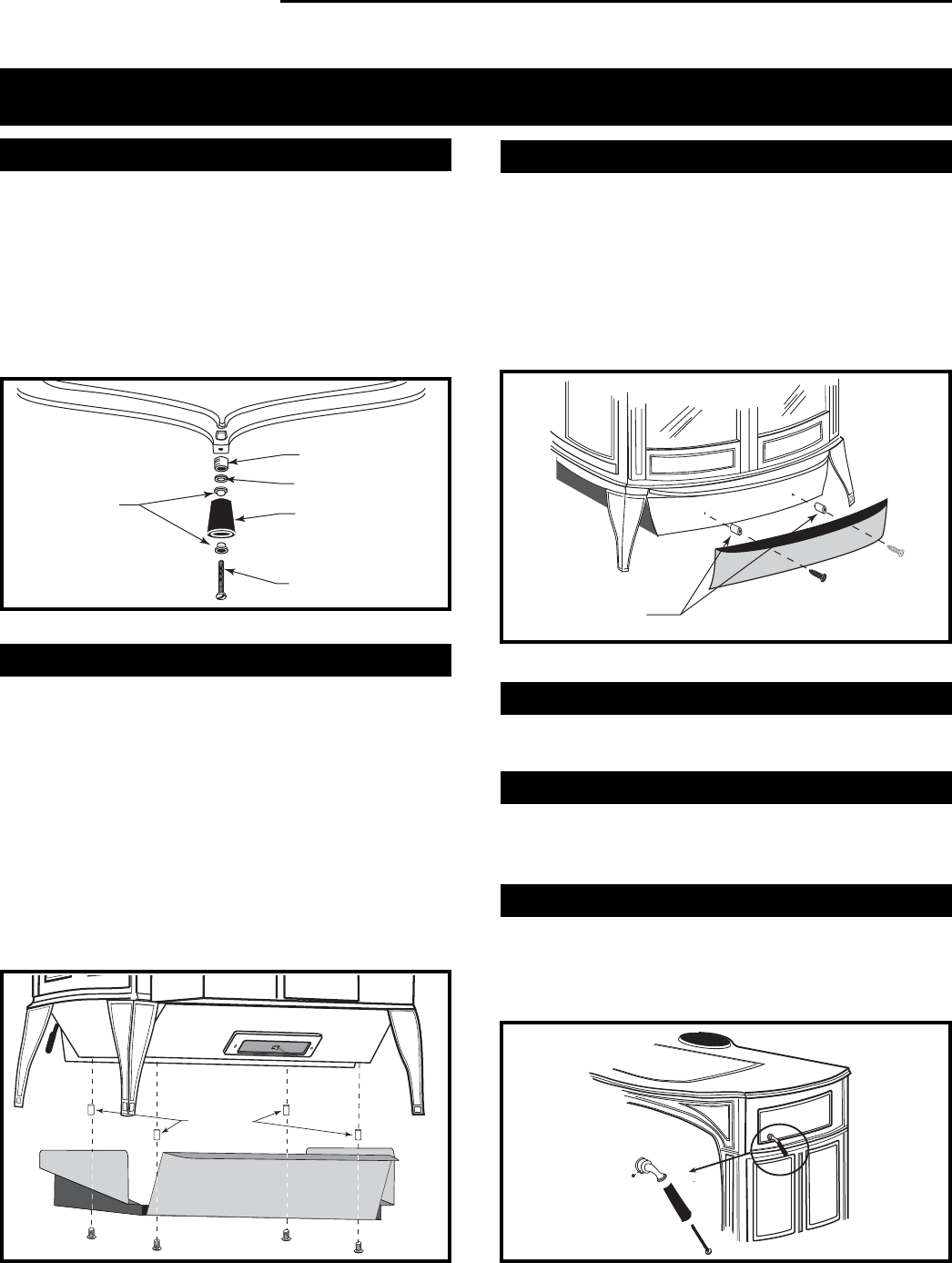
Attach the Primary Air Thermostat Handle
The primary air thermostat handle is the smaller of the
two black handles. Secure the handle to the stub on
the right side of the stove with an 8-32 x 2" slot head
machine screw. (Fig. 19)
D
EFIA
N
T
ST540
Fig. 19 Attach the thermostat handle.
Bushings
Spacer
Knob
Bolt
ST536
Fig. 16 Attach the griddle handle.
Washer