


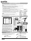

10
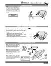
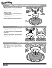
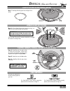
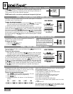
INSTALLING THE SWITCH HOUSING ASSEMBLY
Step A4. Line up the two clearance holes
in the cap with the two threaded holes
on the raised rim of the switch housing.
Press the cap onto the switch housing to
seat the guide pins into the alignment
holes of the switch housing.
Step A5. Using the two (2) 8-32 X
3
/8″
screws removed in Step A1, install the
cap onto the switch housing.
Tighten securely by hand only.
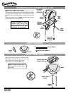
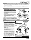
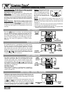
INSTALLING THE CAP
Step A2. Attach the two (2) 5-32 X
9
/32″
switch housing screws removed in Step 8
(on Page 6) to fan motor as shown, leav-
ing
1
⁄
8
" space for the switch housing
installation.
Step A3. Lift the switch housing, run-
ning the switch housing screws through
the keyholes. Turn the switch housing
right (clockwise) to engage the keyholes.
Tighten securely by hand only.
CAP SCREW
8-32 X
3
/8″
(2)
SWITCH HOUSING
MOUNT SCREW
5-32 X
9
/32″
(2)
KEYHOLE
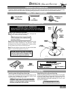
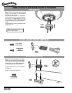
NO LIGHT KIT INSTALLATION
NOTE: THE FOLLOWING STEPS ARE TO
BE PERFORMED
ONLY IF YOU ARE NOT
INSTALLING THE LIGHT KIT!
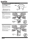
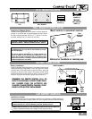
Step A1. Locate the switch housing/cap
assembly and remove the two 8-32 X
3
/8″
screws holding the cap onto the switch
housing.
CAP
SWITCH
HOUSING
CAP SCREW
8-32 X
3
/8″
(2)
Note: Save these two screws–they
will be used in Step A5!