52C
SERIES
8
OPERATION
COMFORT CONTROLS
■
ADJUST AIRFLOW DIRECTION
— The discharge
air grille is mounted on the front panel so that the air
discharges forward. If upward discharge is required,
remove the grille by removing screws on back of front
panel. Rotate grille 180 degrees and reinstall on the
front panel.
■
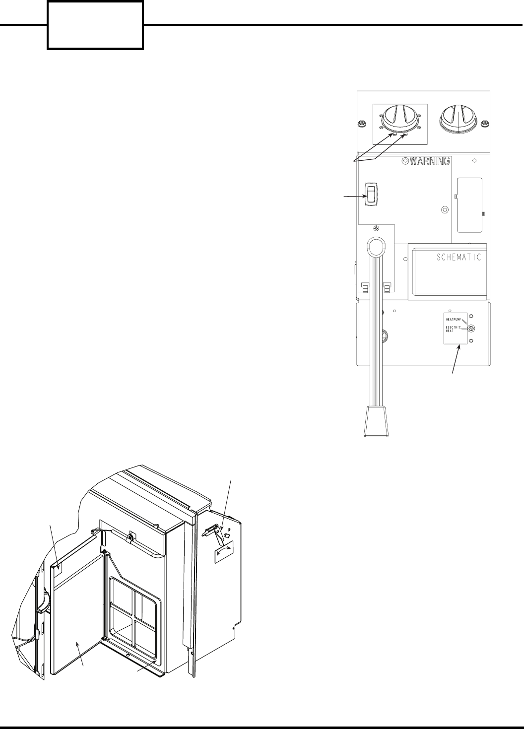
ADJUST VENT —
The vent handle is on the left
side of the unit. Turn handle to open or close vent.
Vent will remain in last desired position until handle
is turned again. Magnet will ensure positive closure.
See Figure 13.
■
SETTING TEMPERATURE LIMITS
— Setting tem-
perature limits on the unit provides the user a
restricted range of temperature control. See Figure 14.
NOTE: This adjustment is optional and is not appli-
cable to remote control units.
The temperature limits are factory set to full range,
which is 60 F to 90 F. To set restricted rotation of the
temperature control knob:
1. Remove front panel.
2. Remove temperature control knob to expose tem-
perature limiter.
3. Remove standoff pins from the 60 F and 90 F indi-
cator holes.
4. Replace standoff pin in hole for desired minimum
temperature.
5. Replace standoff pin in hole for desired maximum
temperature.
6. Reinstall temperature control knob.
7. Reinstall front panel.
NOTE: Temperature indicators stamped on tem-
perature limiter are approximate and represent
degrees F.
80
85
90
60
65
70
75
TEMPERATURE
CONTROL
STANDOFF
PINS
FAN CYCLE
SWITCH
OUTDOOR
THERMOSTAT
(HEAT PUMP
UNITS ONLY)
CON
CYC
FIGURE 14 — 52C OPERATING CONTROLS
VENT
DOOR
VENT
FILTER
MAGNET
O
P
E
N
C
L
O
S
E
VENT HANDLE
FIGURE 13 — 52C VENT DOOR


