7
WALL THERMOSTAT INSTALLATION
The following instructions apply to RC and RP units
only.
NOTE: Carrier thermostats are recommended. See
Accessories section.
■
INSTALL THERMOSTAT —
All remote control
units.
1. Check to be sure power to unit is disconnected.
2. Remove terminal board cover from control box
cover by removing screw (see Figure 10).
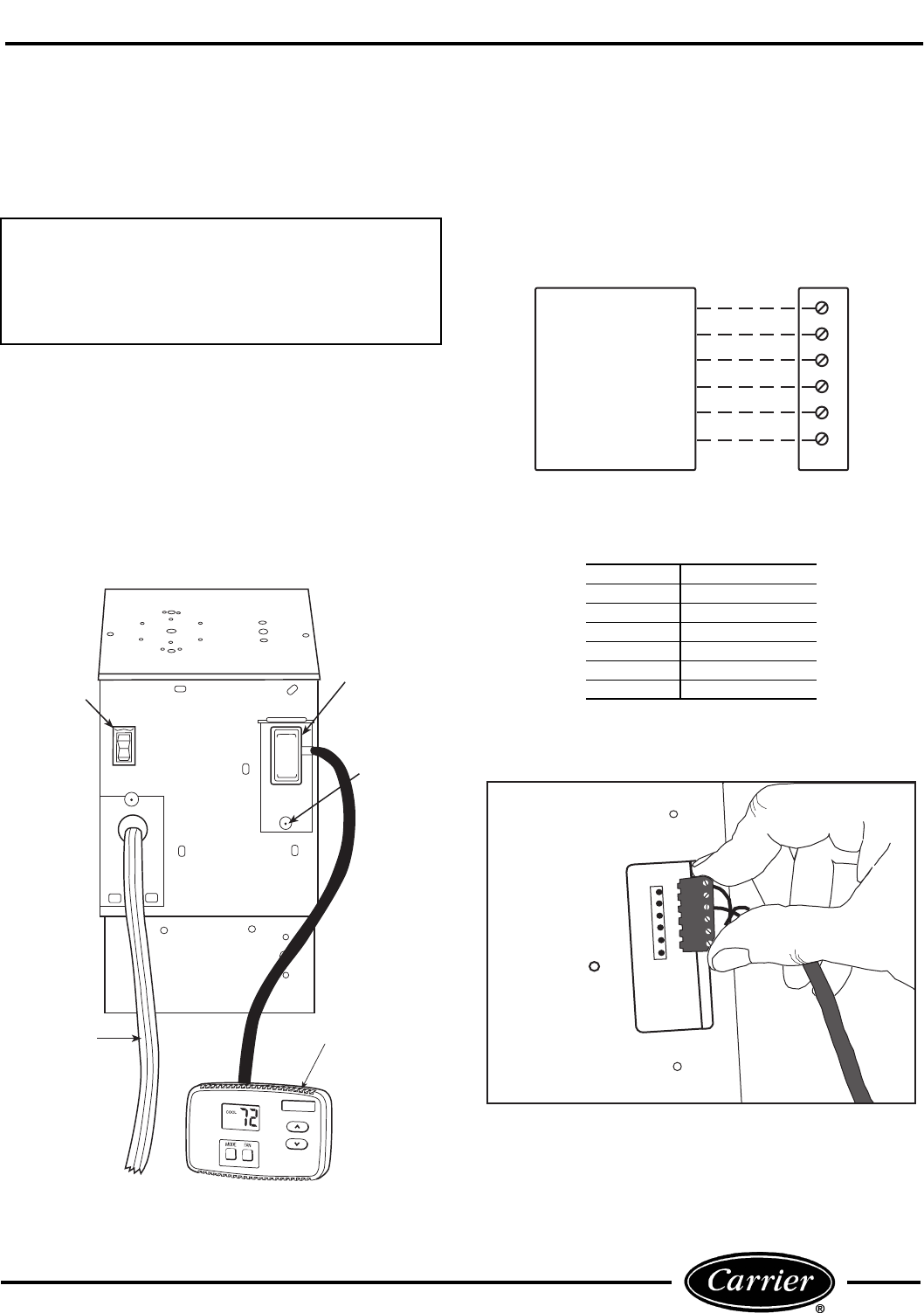
NOTE: Terminal connector can be removed and re-
placed to simplify thermostat wiring.
3. Connect wires from terminals on the thermostat
to terminals on chassis terminal board connector.
See Figures 11 and 12.
4. Reinstall cover.
5. Set desired fan speed using fan switch (unit will
operate only at selected speed).
6. Restore power to unit.
NOTE: Refer to thermostat installation instructions
for details on installing thermostat.
IMPORTANT: Only trained, qualified personnel
and service mechanics should install electrical
accessories on Carrier 52C series products per
Carrier’s installation instructions. Please contact
your local electrical contractor, dealer, or distribu-
tor for assistance.
FAN
SWITCH
POWER
CORD
THERMOSTAT
TERMINAL
COVER
HI
LO
SCREW
FIGURE 10 — CONTROL BOX TERMINAL COVER
TYPICAL
WALL
THERMOSTAT
R
G
Y
W
O
C
52C TERMINAL
BLOCK
R
G
Y
W
O
C
NOTES:
1. Use terminal “O” for heat pump connection only.
2. See table below for terminal descriptions.
FIGURE 11 — WIRING CONNECTIONS
TERMINAL DESIGNATION
R
24 VAC
G
Fan
Y
Compressor
W
Electric Heat
O
Reversing Valve
C
Common
FIGURE 12 — TERMINAL CONNECTOR
REMOVAL AND REPLACEMENT


