


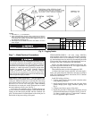
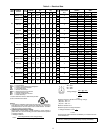
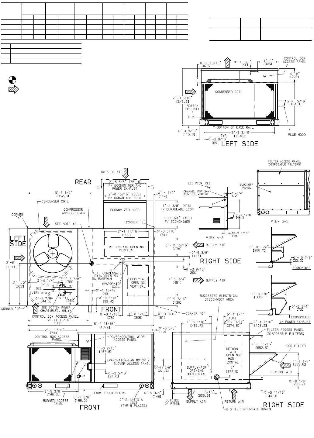
8
UNIT
48TJ
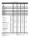
STANDARD
UNIT
WEIGHT
DURABLADE
ECONOMIZER
WEIGHT
ECONOMI$ER
WEIGHT
CORNER
WEIGHT
(A)
CORNER
WEIGHT
(B)
CORNER
WEIGHT
(C)
CORNER
WEIGHT
(D)
Lb Kg Lb Kg Lb Kg Lb Kg Lb Kg Lb Kg Lb Kg
E/F004
460 209 34 15.4 47 21.3 140 63.5 105 47.6 159 72.1 56 25.4
D/E/F005
470 213 34 15.4 47 21.3 142 64.4 106 48.1 162 73.5 60 27.2
D/E/F006
490 222 34 15.4 47 21.3 150 68.0 115 52.2 160 72.6 65 29.5
D/E/F007
565 256 34 15.4 47 21.3 165 74.8 136 61.7 200 90.7 64 29.0
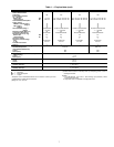
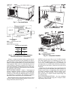
CONNECTION SIZES
A
1
1
/
16
″
″″
″
Dia [27] Field Power Supply Hole
B
3
/
4
″
″″
″
-14 NPT Condensate Drain
C
1
/
2
″
″″
″
-14 NPT Gas Connection
NOTES:
1. Dimensions in [ ] are in millimeters.
2. Center of gravity.
3. Direction of airflow.
4. On vertical discharge units, ductwork to be attached to accessory roof curb only. For horizontal dis-
charge units, field-supplied flanges should be attached to horizontal discharge openings, and all
ductwork should be attached to the flanges.
5. Minimum clearance (local codes or jurisdiction may prevail):
a. Between unit, flue side and combustible surfaces, 36 inches.
b. Bottom of unit to combustible surfaces (when not using curb), 1 inch.
Bottom of base rail to combustible surfaces (when not using curb) 0 inches.
c. Condenser coil, for proper airflow, 36 in. one side, 12 in. the other. The side getting the greater
clearance is optional.
d. Overhead, 60 in. to assure proper condenser fan operation.
e. Between units, control box side, 42 in. per NEC.
f. Between unit and ungrounded surfaces, control box side, 36 in. per NEC.
g. Between unit and block or concrete walls and other grounded surfaces, control box side, 42 in.
per NEC.
h. Horizontal supply and return end, 0 inches.
6. With the exception of the clearance for the condenser coil and combustion side as stated in notes
5a, b and c, a removable fence or barricade requires no clearance.
7. Units may be installed on combustible floors made from wood or Class A, B, or C roof covering
material if set on base rail.
8. The vertical center of gravity is 1
′
-6
″
[457] up from the bottom of the base rail.
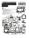
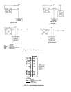
BOTTOM POWER CHART, THESE HOLES REQUIRED FOR
USE WITH ACCESSORY PACKAGES — CRBTMPWR001A00,
(POWER AND CONTROL) AND CRBTMPWR003A00
(POWER, CONTROL, AND GAS)
THREADED
CONDUIT SIZE
WIRE
USE
REQURED
HOLE SIZES (MAX.)
1
/
2
″
″″
″
24 V
7
/
8
″
″″
″
[22.2]
3
/
4
″
″″
″
Power 1
1
/
8
″
″″
″
[28.4]
1
/
2
″
″″
″
FPT
Gas 1
1
/
4
″
″ ″
″
[31.8]
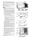
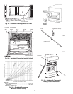
Fig. 6 — Base Unit Dimensions