


3
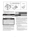
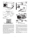
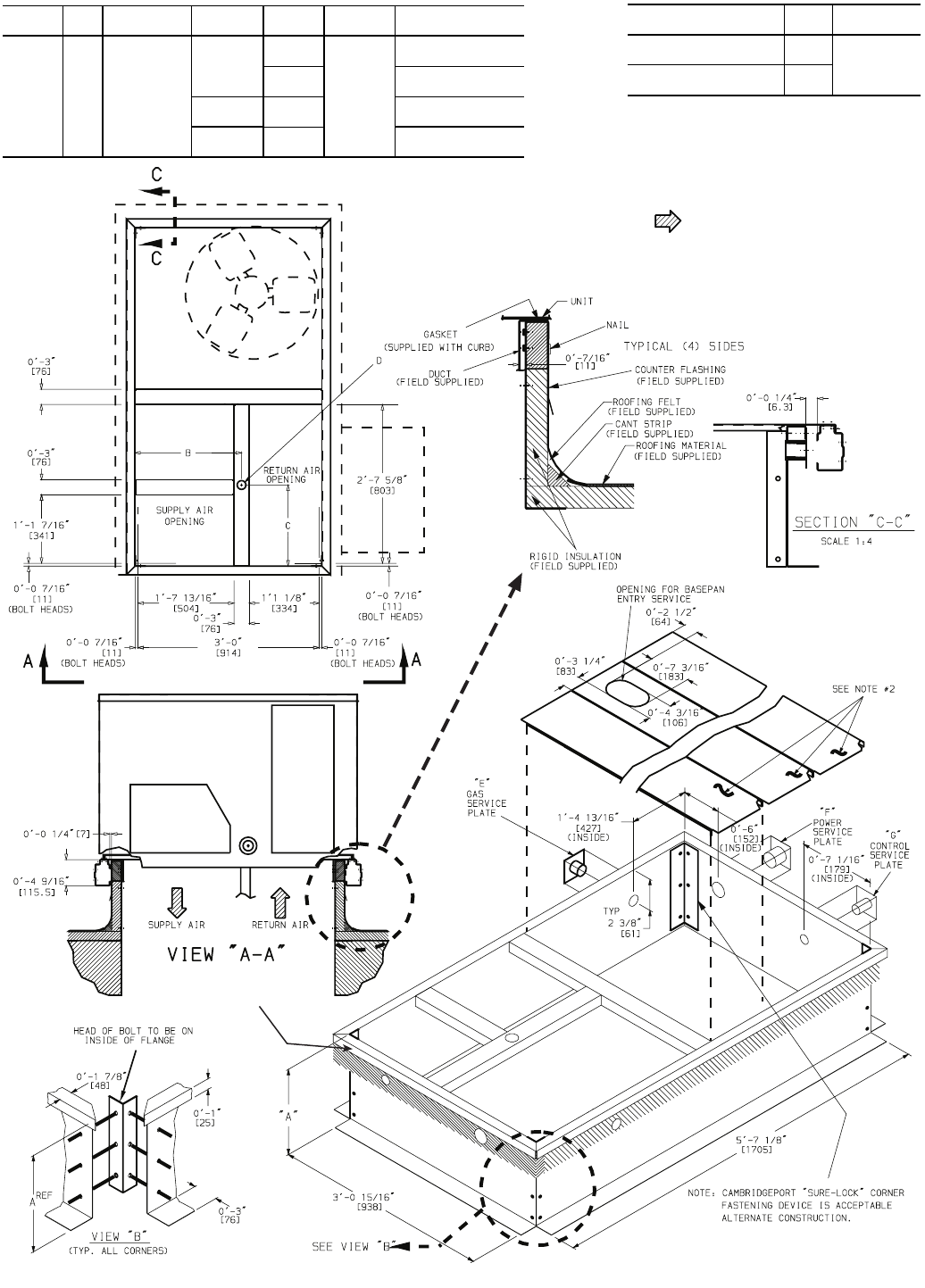
TO ENSURE AIRTIGHT CONNECTION
PLACE UNIT AS CLOSE TO
END AS POSSIBLE.
TO ENSURE AIRTIGHT CONNECTION
PLACE UNIT AS CLOSE TO
END AS POSSIBLE.
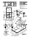
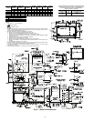
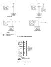
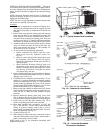
Fig. 2 — Roof Curb Dimensions
ROOF CURB
ACCESSORY
‘‘A’’
UNIT SIZE
48TJ
CRRFCURB001A00
1′-2″
[356]
004-007
CRRFCURB002A00
2′-0″
[610]
NOTES:
1. Roof curb accessory is shipped disassembled.
2. Insulated panels:
3. Dimensions in [ ] are in millimeters.
4. Roof curb: galvanized steel.
5. Attach ductwork to curb (flanges of duct rest on
curb).
6. Service clearance 4′ on each side.
7. Direction of airflow.
8. Connector packages CRBTMPWR001A00 and
2A00 are for thru-the-curb type. Packages
CRBTMPWR003A00 and 4A00 are for the thru-
the-bottom type connections.
‘‘B’’ ‘‘C’’
‘‘D’’ ALT
DRAIN HOLE
‘‘E’’
Gas
“F”
Power
“G”
Control
CONNECTOR
PKG ACY
1′-9
11
/
16
″
[551]
1′-4″
[406]
1
3
/
4
″
[44.5]
3
/
4
″
[19] NPT
3
/
4
″
[19] NPT
1
/
2
″
[12.7] NPT
CRBTMPWR001A00
1
1
/
4
″
[31.7]
CRBTMPWR002A00
1
/
2
″
[12.7] NPT
3
/
4
″
[19] NPT
CRBTMPWR003A00
3
/
4
″
[19] NPT
1
1
/
4
″
[31.7]
CRBTMPWR004A00