


MORNING WARM-UP (VAV Only) (Stand-Alone Opera-
tion) — When the unit operates in stand-alone mode, morn-
ing warm-up occurs when the unit is energized in Occupied
mode and return-air temperature(RAT) is below 68 F. Warm-up
will not terminate until the RAT reaches 68 F. The heat in-
terlock relay output is energized during morning warm-up.
(A field-installed 24-vdc heat interlock relay is required.) The
output will be energized until the morning warm-up cycle is
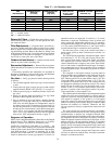
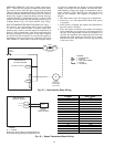
complete. Refer to Fig. 42 for heat interlock relay wiring.
SPACE TEMPERATURE RESET SENSOR (VAV Only) —
An accessory space temperature sensor wired to terminals
T1 and T2 on the control module is required. Space tem-
perature reset is used to reset the supply-air temperature set
point of a VAV system higher, as the space temperature falls
below the Occupied Cool set point. As the space tempera-
ture falls below the Occupied Cool set point, the supply-air
temperature will be reset upward as a function of the reset
ratio. (Default is 3.) Reset ratio is expressed in degrees change
in supply-air temperature per degree of space temperature
change. A reset limit will exist which will limit the maxi-
mum number of degrees the supply-air temperature may be
raised. (Default is 10 F.) Both the reset ratio and the reset
limit are user definable. The sequence of operation is as
follows:
1. The on/off status of the unit supply fan is determined.
2. If the fan is ‘‘on,’’ the sequence will check if the system
is occupied.
3. If the system is occupied, the sequence will determine if
the reset option is enabled.
4. If the reset option is enabled, the sequence will read the
space temperature and compare it to the Occupied Cool
set point. If the temperature is below the Occupied Cool
set point, the algorithm will compute the reset value and
compare this value against the reset limit. If it is greater
than the reset limit, the sequence will use the reset limit
as the reset value.
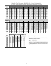
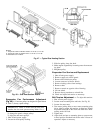
BASE MODULE
CONTROL BOARD
T
30
T29
T
28
COM
COM
B
TRAN2
SECONDARY
24 VOLT
CB4
3.2 AMPS
INDOOR FAN RELAY
HIR
FIELD
INSTALLED
(HN61KK040)
(24V, 9.5VA)
LEGEND
CB — Circuit Breaker
COM — Common
HIR — Heat Interlock Relay
T—Terminal
TRAN — Transformer
Fig. 42 — Heat Interlock Relay Wiring
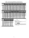
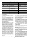
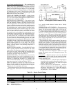
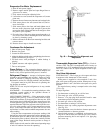
4-20 mA
INPUT
FIELD
SUPPLIED
INPUT DEVICE
BASE MODULE
CONTROL BOARD
(+) T11
(–) T12
LEGEND
T—Terminal
NOTE: The 4 to 20 mA input is a field-supplied non-
Carrier EMS (Energy Management System)device.
Fig. 43 — Space Temperature Reset Wiring
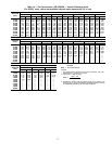
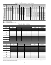
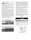
mA INPUT DEG. F RESET
4 0.00
5 1.25
6 2.50
7 3.75
8 5.00
9 6.25
10 7.50
11 8.75
12 10.00
13 11.25
14 12.50
15 13.75
16 15.00
17 16.25
18 17.50
19 18.75
20 20.00
42