


To set the VFD, the VFD must be powered up; however,
since it is located near the indoor air fan, operation of the
fan is not desirable. To disable the fan, perform the follow-
ing procedure:
1. Open the indoor fan circuit breaker.
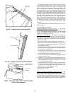
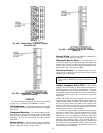
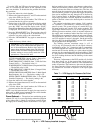
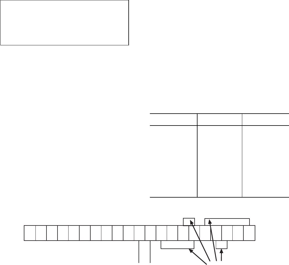
2. Remove the jumper between CC and ST on the terminal
strip of the VFD (see Fig. 41).
3. Close the indoor fan circuit breaker. The VFD now is
powered but the fan will not operate.
4. On the front of the VFD is a keypad and display which
will be used to enter the set point. To access this field,
press the ‘‘PRG’’ key until the display reads ‘‘S.PrG’’
(Speed Group Parameters). Press thearrow keyuntil ‘‘Sr1’’
is displayed. This is the VFD set point listed in Table 7.
5. Press the ‘‘READ/WRITE’’key. The set point value will
be displayed. Use the up-arrow or down-arrow key to
adjust the set point value to the value desired.
6. Press the ‘‘READ/WRITE’’ key again to enter the new
value.
7. Check the factory default values.
IMPORTANT: The Carrier factory default values
for the VFD may be different than the default val-
ues of the manufacturer. Refer to the Carrier lit-
erature when checking defaultvalues. The following
default values have been changed from the manu-
facturer settings to more closely match the VFD
operation to a Carrier VAV unit.
SETUP PARAMETERS (Item 6, Point 1, Output Fre-
quency) — The default value should be 20.
JUMP FREQUENCY GROUP (Item 7, PID Set Point
Control Select) — The default value is 1.
JUMP FREQUENCYGROUP(Item 8,Proportional Gain)
— The default value is 100.
JUMP FREQUENCY GROUP (Item 9, Integral Gain)
— The default value is 50.
SPEED GROUP PARAMETERS (Item 2, Multi-Speed
Run Frequency No. 1) — The factory setting is 30.
SPEED GROUP PARAMETERS (Item 2, Fire Speed
Override Frequency) — The factory setting is 60.
8. Open the indoor fan circuit breaker.
9. Replace the jumper between CC and ST on the terminal
strip of the VFD.
10. Close the indoor fan circuit breaker; the VFD now is
powered and the fan will operate.
NOTE: Any field measurement of supply fan amps must be
taken with an RMS meter between the fan circuit breaker
and fan contactor (upstream of VFD).
Power Exhaust — The optional non-modulating power
exhaust (CV only) is a two-stage design where the operation
of the exhaust fans is linked to economizer position. When
the supply fan is running and the economizer is 25% open,
the base module closes contacts, activating two exhaust fans.
When the economizer position reaches 75% open, the base
module activates the other two exhaust fans. The fans will
turn off when the economizer closes below the same points.
The economizer position set points that trigger the exhaust
fans can be modified, but only through use of the Service
Tool, Comfort Works, or Building Supervisor software. If
single-stage operation is desired, adjust the economizer set
points to identical values at the desired point to activate all
exhaust fans.
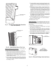
The optional modulating power exhaust (VAV standard,
CV optional) is controlled by a modular electronic se-
quencer system. This system consists of a model R353 sig-
nal input module and 4 model S353 staging modules. The
signal input module receivesa0to10vdcsignal from the
building pressure transducer, which is mounted adjacent to
the supply static transducer behind the filter access panel.
The modules are mounted just below the unit control board.
The left module is the R353, and the 4 modules on the right
are S353 modules for stages 1 through 4. On the unit wiring
label, the R353 is designated PESC, and the S353 modules
are designated PES1 through PES4.
The building pressure transducer range is −0.5 to
+ 0.5 in. wg. It is powered bya0to10vdcsignal. A factory-
installed hose at the ‘‘Lo’’ connection leads to atmosphere,
and a field-supplied hose must be connected to the ‘‘Hi’’ con-
nection and led into the building to a point where building
pressure is to be controlled (positive-pressure building). There
is a plug button in the bulkhead just above the transducers,
for use in leading the hoses into the building via the return
air ductwork.
There are 3 adjustments at the R353 module, all of which
have been factory set. In the center of the circuit board is
a set of 4 pins with a jumper, labeled J2. This determines the
mode of operation. The bottom two pins must be jumpered
for direct operation. Direct operation means that the stag-
ing modules are activated in sequence as the input signal
increases.
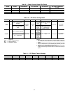
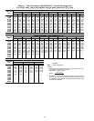
Table 7 — VFD Supply Air Pressure Set Point
PRESSURE
(in. wg)
CONTROL
(mA)
VFD
SET POINT
0 4.0 0
0.25 4.8 3
0.50 5.6 6
0.75 6.4 9
1.00 7.2 12
1.25 8.0 15
1.50 8.8 18
1.75 9.6 21
2.00 10.4 24
2.25 11.2 27
2.50 12.0 30
2.75 12.8 33
3.00 13.6 36
3.25 14.4 39
3.50 15.2 42
VFD — Variable Frequency Drive
(SS2)
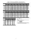
(SS3)
FLA FLB FLC P24 RCH LOW FM AM PP RR IV CC ST F R CC SS1 JOG AD2 RST CC
+
–
DPDP
JUMPERS
NOTE: Terminal strip is located insidethe VFD at the bottom.
Fig. 41 — VFD Factory-Installed Jumpers
32