


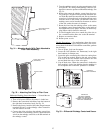
Differential Enthalpy Sensor Installation — To install the con-
trol, perform the following procedure:
1. Turn off all power. Ensure disconnect is locked out.
2. Remove the economizer inlet filters from the bottom of
the right hand economizer hood. See Fig. 24.
3. Remove the factory-installed, 620-ohm jumper between
terminals SR and + on the enthalpy control located in-
side the outdoor air hood.
4. Connect the violet wire from the enthalpy sensor kit to
the + terminal on the enthalpy control. Connect the blue
wire from the enthalpy sensor kit to the SR terminal on
the enthalpy control.
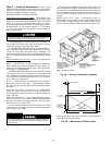
5. Turn the enthalpy control set point potentiometer clock-
wise past the ‘‘D’’setting on the enthalpy control to con-
figure the control to operate on differential enthalpy. See
Fig. 34.
6. Remove the return-air enthalpy sensor from the acces-
sory package. Using the screws provided, mount the sen-
sor inside the return duct near the unit. Do not locate the
control too far from the unit, or the wires will not reach
from the sensor to the control. On 48EW/EY units, the
enthalpy sensor can be installed in the return air section
of the unit, under the return air dampers.
7. Route the wires from the enthalpy sensor to the return
air enthalpy control through the holes on the inside of
the hinged filter access panel. The holes are blocked by
plug buttons which should be removed.
8. Use field-supplied wire ties to attach the violet wire to
the + terminal and the blue wire to the SR terminal.
9. Replace economizer filters.
10. Return power to unit.
Disable Economizer — For applications where the econo-
mizer will not be used (areas of high humidity), the econo-
mizer should be disabled. To disable the economizer, perform
the following:
1. Turn of power. Lock out disconnect.
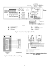
2. Locate the OAT (Outdoor Air Thermostat) in the right
hand outdoor air damper area.
3. Locate the splice connecting the violet wire coming from
T24 on the base module board to the red wire coming
from T29 on the base module board. Remove the wire
nut and break the red to violet wire splice.
4. Cap off both wires. When the connection is broken the
base module is fooled into thinking that the enthalpy is
not acceptable and economizer operation is disabled.
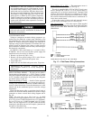
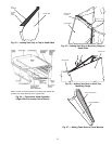
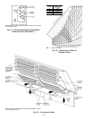
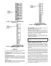
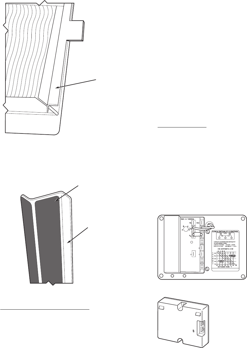
MOUNTING ANGLE
(WITH TABS)
Fig. 31 — Mounting Angle (With Tabs) Attached to
Filter Track Assembly
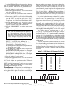
BLACK SEAL STRIP
(CENTERED)
FILTER COVER
Fig. 32 — Attaching Seal Strip to Filter Cover
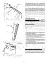
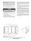
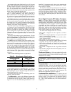
HH57AC077
ENTHALPY CONTROL
+
C7400A1004
Fig. 33 — Differential Enthalpy Control and Sensor
HH57AC078
ENTHALPY SENSOR
(USED WITH ENTHALPY
CONTROL FOR DIFFERENTIAL
ENTHALPY OPERATION)
27