


When a VAV unit with a space temperature sensor is ac-
cessed via a computer, the following additional features are
available:
• ability to initiate timed override from T-55 sensors
• temperature compensated start to calculate early start time
before occupancy
• provide space temperature reset to reset the supply air set
point upward when the temperature falls below the occu-
pied cooling set point
An electronic expansion board may be field-installed to
provide the following features:
• fan status
• filter status
• field-applied status
• demand limiting
• IAQ Sensor
• OAQ Sensor
• alarm light
• fire unit shutdown
• fire pressurization
• fire evacuation
• fire smoke purge
When the unit is connected to the CCN (Carrier Comfort
Network), the following expansion board features can be
utilized:
• CCN IAQ (indoor air quality) participation
• CCN OAQ (outdoor air quality) participation
• CCN demand limit participation
• modulated power exhaust override
• ability to use multiple space temperature sensors (mul-
tiples of 4 and 9 only) to average space temperature (DAV
only)
Afield-supplied T-55 space temperature sensor can be added
to monitor room temperature and provide unoccupied over-
ride capability (1 hour).
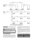
When the unit is equipped with a field-supplied space tem-
perature sensor and a remote contact closure (remote start/
stop) the occupied default set points will monitor unit op-
eration. The occupied default set points are 55 F (supply air)
cooling and 68 F (return air temperature) heating. See
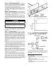
Fig. 14 for remote start/stop wiring.
NOTE: For units without a space temperature sensor and which
have not had the base unit control board accessed via soft-
ware to set an occupancy schedule, the remote start/stop clo-
sure will allow the unit to operate in the pre-configured oc-
cupied default set points of 55 F (supply-air temperature)
cooling and 68 F (return-air temperature) heating. Without
an occupancy schedule, the unit will control to the unoccu-
pied default set points of 90 F (return air) cooling and 55 F
(return air) heating.
Features with NetworkApplications — The base controlboard
provides, as standard, a connection for use with a Carrier
Comfort System and can also be integrated into a Carrier
Comfort Network. When the unitis accessed via a PC equipped
with ComfortWorks™, Building Supervisor, or Service Tool
software or LID-2B accessory, the following features can be
accessed:
• on-board timeclock can be programmed
• occupancy schedules can be programmed
• unit set points can be changed
• alarms can be monitored
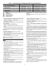
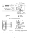
This access is available on the base control board via a
RJ-11 phone jack or a 3-wire connection to the communi-
cation bus. See Fig. 16. The internal timeclock has a 10-hour
minimum back-up time to provide for unit power off for ser-
vicing unit or during unexpected power outages. For com-
plete Carrier Comfort System (CCS) or Carrier Comfort
Network (CCN) features and benefits, refer to the product
literature.
Step 8 — Make Electrical Connections
POWER WIRING — Units are factory wired for the voltage
shown on the unit nameplate.
When installing units, provide a disconnect per NEC
(National Electrical Code) of adequate size (MOCP [maxi-
mum overcurrent protection] of unit is on the informative
plate). All field wiring must comply with NEC and all local
codes. Size wire based on MCA(minimum circuit amps) on
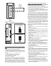
the unit informative plate. See Fig. 17 for power wiring con-
nections to the unit power terminal blockand equipment ground.
The main power terminal block is suitable for use with
aluminum or copper wire. See Fig. 17. Units have circuit
breakers for compressors, fan motors, and control circuit. If
required by local codes, provide an additionaldisconnect switch.
Whenever external electrical sources are used, unit must be
electrically grounded in accordance with local codes, or in
absence of local codes, with NEC, ANSI C1-latest year.
All field wiring must comply with NEC and local code
requirements.
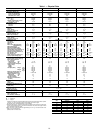
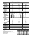
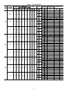
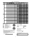
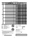
FIELD POWER SUPPLY — Unit is factory wired for volt-
age shown on unit nameplate. See Table 4 for electrical data.
Field wiring can be brought into the unit from bottom
(through basepan and roof curb) or through side of unit (cor-
ner post next to control box).
A3
1
⁄
2
-in. NPT coupling for field power wiring and a
3
⁄
4
-in. NPT coupling for 24-v control wiring are provided in
basepan. In the side post, there are two 2
1
⁄
2
-in. (024-034) or
3-in. (038-048) knockouts for the field power wiring. See
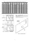
Fig. 3-6. If control wiring is to be brought in through the
side of unit, a
7
⁄
8
-in. diameter hole is provided in the con-
denser side post next to the control box.
If disconnect box is mounted to corner post, be careful
not to drill any screws into the condenser coil.
Routing Through Bottom of Unit — If wiring is brought in
through bottom of unit, use field-supplied watertight conduit
to run power wiring from basepan out through bottom
3
1
⁄
2
-in. hole to the disconnect box and back into unit to the
main control box.
Use strain relief going into control box through 2
1
⁄
2
-in.
diameter hole provided. After wires are in unit control box,
connect to power terminal block (see Power Wiring section
above).
Low-voltage wiring must be run in watertight conduit from
the basepan to control box and through
7
⁄
8
-in. diameter hole
provided in bottom of unit control box. Field-supplied strain
relief must be used going into the box. After wiring is in
control box, make connections to proper terminals on ter-
minal blocks (see Field Control Wiring section on page 21).
Install conduit connector in unit basepan as shown in
Fig. 3-6. Route power and ground lines through connector to
terminal connections in unit control box as shown on unit
wiring diagram and Fig. 17.
Routing Through Side of Unit — Route power wiring in field-
supplied watertight conduit into unit through 2
1
⁄
2
-in. hole.
See Fig. 17.
Use field-supplied strain reliefgoing intocontrol box through
2
1
⁄
2
-in. diameter hole provided. After wires are in unit con-
trol box, connect to power terminal block (see Power Wiring
section on this page).
Bring low-voltage control wiring through factory-drilled
7
⁄
8
-in. diameter hole in condenser side post. Use strain relief
going into
7
⁄
8
-in. diameter hole in bottom of unit control box.
After wiring is in control box, make connection to proper
terminals on terminal blocks (see Field Control Wiring sec-
tion on page 21).
16