


9
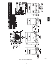
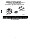
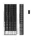
Horizontal Duct Covers
A09076
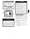
Basepan
Downflow
(Vertical)
Supply
Knockout
Basepan
Downflow
(Vertical)
Return
Knockout
A09093
Fig. 9 -- Supply and Return Duct Opening
Step 8 — Install Electrical Connections
ELECTRICAL SHOCK HAZARD
Failure to follow this warning could result in personal
injury or death.
The unit cabinet must have an uninterrupted, unbroken
electrical ground to minimize the possibility of personal
injury if an electrical fault should occur. This ground may
consist of an electrical wire connected to the unit ground
screw in the control compartment, or conduit approved for
electrical ground when installed in accordance with NFPA
70 (NEC) (latest edition) (in Canada, Canadian Electrical
Code CSA C22.1) and local electrical codes.
!
WARNING
UNIT COMPONENT DAMAGE HAZARD
Failure to follow this caution may result in damage to the
unit being installed.
1. Make all electrical connections in accordance with
NFPA 70 (NEC) (latest edition) and local electrical codes
governing such wiring. In Canada, all electrical
connections must be in accordance with CSA s tandard
C22.1 Canadian Electrical Code Part 1 and applicable
local codes. Refer to unit wiring diagram.
2. Use only copper conductor for connections between
field--supplied electrical disconnect switch and unit. DO
NOT USE ALUMINUM WIRE.
3. Be sure that high--voltage power to unit is within
operating voltage range indicated on unit rating plate. On
3--phase units, ensure phases are balanced within 2
percent. Consult local power company for correction of
improper voltage and/or phase imbalance.
4. Do not damage internal components when drilling
through any panel to mount electrical hardware, conduit,
etc.
!
CAUTION
HIGH--VOLTAGE CONNECTIONS
The unit m ust have a separate electrical service with a
field--supplied, waterproof disconnect switch mounted at, or within
sight from the unit. Refer to the unit rating plate, NEC and local
codes for maximum fuse/circuit breaker size and minimum circuit
amps (ampacity) for wire sizing.
The field--supplied disconnect may be mounted on the unit over
the high--voltage inlet hole when the standard power and
low--voltage entry points are used. See Fig. 2 and 3 for acceptable
location.
See unit wiring label (Fig. 12, 13 and 14) and Fig. 10 for reference
when making high voltage connections. Proceed as follows to
complete the high--voltage connections to the unit.
Single phase units:
1. Run the high-- voltage (L1, L2) and ground lead into the
control box.
2. Connect ground lead to chassis ground connection.
3. Locate the black and yellow wires connected to the line side
of the contactor.
4. Connect field L1 to black wire on connection 11 of the
compressor contactor.
50VL--A