


14
HIGH LOW COM
QC5
QC4
QC3
KZ
KL
07 09 080L0
ALO
R13 C8 R11 Q1
Q3
D2
AL2
DCR QCR
QC1
C
RL
01
G1
G2
Z1
A7 R9 AB A15
C4
C9
C0
QIL Z2 06 04
U1
C3
R4 RL4
JWZ
C7
D5 D3
R3 R5 R6
R2
JW5
QCB
Y
R W2Y C W3W3W2W2C
JW4
P2 JW3
P4
P1
W2W3
Y2 Y1
YDH
GCR
SSTZ-8
P3
SDL
24VAC/R3AMP CDM/C
F1
STD
DEHUM
A09059
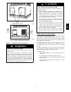
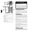
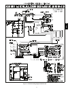
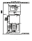
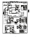
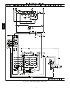
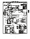
Fig. 11 -- Interface Fan Board (IFB)
SINGLE SPEED COOLING WITH HIGHER
ELECTRIC HEAT
SPEED
This unit can also be configured to operate with single speed
cooling and a higher speed for an accessory electric heater .
1. Using Fig. 11, move the two pin DEHUM jumper from the
“STD” position to the “DEHUM” position.
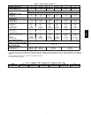
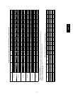
2. See Table 2 for minimum airflow for electric heat operation.
Add electric heater and filter pressure drop to duct system
static pressure to determine total external static pressure.
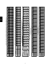
3. Select speed tap from T able 4 that will achieve required
airflow from Table 2.
4. Remove the vinyl cap off of the desired speed tap wire
(Refer to Table 3 for color coding).
5. Connect the desired speed tap wire to the “HIGH” terminal
on the interface fan board (IFB).
UNIT OPERATION HAZARD
Failure to follow this caution may result in unit component
damage or improper operation.
To use this mode, a speed connection must be made on the
“HIGH” terminal that meets or exceeds the minimum
airflow found in Table 2.
!
CAUTION
Table 3 – Color Coding for Indoor Fan Motor Leads
Black = High Speed
Orange = Med--High Speed
Red = Med Speed
Pink = Med--Low Speed
Blue = Low Speed
ELECTRICAL SHOCK HAZARD
Failure to follow this warning could result in personal
injury or death.
Disconnect electrical power to the unit and install lockout
tag before changing blower speed.
!
WARNING
CONTINUOUS FAN OPERATION
When the DEHUM feature is not used, the continuous fan speed
will be the same as cooling fan speed. When the DEHUM feature
is used, the continuous fan will operate on IFB “LOW” speed
when the DH c ontrol lead is not energized, or IFB “HIGH” speed
when the DH lead is ener gized (see Fig. 11).
COOLING SEQUENCE OF OPERATION
With the room thermostat SYSTEM switch in the COOL position
and the FAN switch in the AUTO position, the cooling sequence of
operation is as follows:
When the room temperature rises to a point that is slightly above
the cooling control setting of the thermostat, the thermostat
completes the circuit between thermostat terminal R to t erminals Y
and G. These completed circuits through the thermostat connect
contactor coil (C) (through unit wire Y) and time delay relay
(TDR) (through unit wire G) across the 24--V secondary of
transformer (TRAN).
The normally open contacts of energized contactor (C) close and
complete the circuit through compressor motor (COMP) to
condenser (outdoor) fan motor (OFM). Both motors start instantly.
A set of normally open contacts on the interface fan board (IFB)
are closed which energizes a circuit to the indoor fan motor (IFB).
NOTE: Once the compressor has started and then has stopped, it
should not be started again until 5 minutes have elapsed.
The cooling cycle remains on until the room temperature drops to a
point that is slightly below the cooling control setting of the room
thermostat. At this point, the thermostat breaks the circuit between
thermostat terminal R to terminals Y and G. These open circuits
deenergize contactor coil C and IFB. The condenser and
compressor motors stop. After a 90--second delay, the blower
motor stops. The unit is in a standby condition, waiting for the next
call for cooling from the room thermostat.
50VL--A