


2
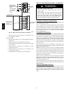
ELECTRICAL SHOCK HAZARD
Failure to follow this warning could result in personal
injury or death.
Before installing or servicing system, always turn off main
power to system and install lockout tag. There may be
more than one disconnect switch. Turn of f accessory heater
power switch if applicable.
!
WARNING
PERSONAL INJURY AND ENVIRONMENTAL
HAZARD
Failure to relieve system pressure could result in personal
injury and/or death.
1. Relieve pressure and recover all refrigerant before
servicing existing equipment, and before final unit disposal.
Use all service ports and open all flow--control devices,
including solenoid valves.
2. Federal regulations require that you do not vent
refrigerant into the atmosphere. Recover during system
repair or final unit disposal.
!
WARNING
CUT HAZARD
Failure to follow this caution may result in personal injury .
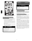
When removing access panels (see Fig. 17) or performing
maintenance functions inside your unit, be aware of sharp
sheet metal parts and screws. Although special care is taken
to reduce sharp edges to a minimum, be extremely careful
when handling parts or reaching into the unit.
!
CAUTION
INTRODUCTION
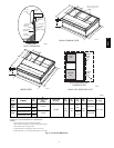
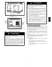
The 50VL-- A packaged air conditioner is fully self--contained and
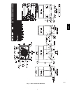
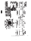
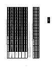
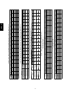
designed for outdoor installation (See Fig.1 ). See Fig. 2 and 3 for
unit dimensions. All unit sizes have discharge openings for both
horizontal and downflow configurations, and are factory shipped
with all downflow duct openings covered. The unit may be
installed either on a rooftop or on a ground--level cement slab. (See
Fig. 4 for roof curb dimensions.)
RECEIVING AND INSTALLATION
Step 1 — Check Equipment
IDENTIFY UNIT
The unit model number and serial number are printed on the unit
informative plate. Check this information against shipping papers.
INSPECT SHIPMENT
Inspect for shipping damage before removing packaging materials.
If unit appears to be damaged or is torn loose from its anchorage,
have it examined by transportation inspectors before removal.
Forward claim papers directly to transportation company.
Manufacturer is not responsible for any damage incurred in transit.
Check all items against shipping list. Immediately notify the
nearest equipment distribution office if any item is missing. To
prevent loss or damage, leave all parts in original packages until
installation.
If the unit is to be mounted on a curb in a downflow application,
review Step 7 to determine which method is to be used to remove
the downflow panels before r igging and lifting into place. The
panel removal process may require the unit to be on the ground.
Step 2 — Provide Unit Support
IMPORTANT: The unit must be secured to the curb by installing
screws through the bottom of the curb flange and into the unit base
rails. When installing large base units onto the common curb, the
screws must be installed before allowing the full weight of the unit
to rest on the curb. A minimum of six screws are required for large
base units. Failure to secure unit properly could result in an
unstable unit. See Warning near Rigging/Lifting information and
accessory curb instructions for more details.
For hurricane tie downs, contact distributor for details and PE
(Professional Engineering) Certificate if required.
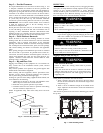
ROOF CURB
Install accessory roof curb in accordance with instructions shipped
with curb (See Fig. 4). Install insulation, cant strips, roofing, and
flashing. Ductwork must be attached to curb.
IMPORTANT: The gasketing of the unit to the roof curb is
critical for a water tight seal. Install gasketing material supplied
with the roof curb. Improperly a pplied gasketing also can result in
air leaks and poor unit performance.
Curb should be level to within 1/4 in. (6.35 mm) (See Fig 6). This
is necessary for unit drain to function properly . Refer to accessory
roof curb installation instructions for additional information as
required.
Installation on older “G” series roof curbs.
Two accessory kits are available to aid in installing a new “ G”
series unit on an old “G” roof curb.
1. Accessory kit number CPADCURB001A00, (small chassis)
and accessory kit number CPADCURB002A00, (large
chassis) includes roof curb adapter and gaskets for the
perimeter seal and duct openings. No additional
modifications to the curb are required when using this kit.
2. An alternative to the adapter curb is to modify the existing
curb by removing the outer horizontal flange and use
accessory kit number CPGSKTKIT001A00 which includes
spacer blocks (for easy alignment to existing c urb) and
gaskets for the perimeter seal and duct openings. This kit is
used when existing curb is modified by removing outer
horizontal flange.
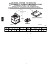
UNIT/STRUCTURAL DAMAGE HAZARD
Failure to follow this caution may result in property
damage.
Ensure there is sufficient clearance for saw blade when
cutting the outer horizontal flange of the roof curb so there
is no damage to the roof or flashing.
!
CAUTION
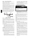
SLAB MOUNT
Place the unit on a solid, level concrete pad that is a minimum of 4
in. (102 mm) thick with 2 in. (51 mm) above grade. The slab
should extend approximately 2 in. (51 mm) beyond the casing on
all 4 sides of the unit (See Fig. 7 ). Do not secure the unit to the slab
except when required by local codes.
50VL--A