


12
PRE--START--UP
ENVIRONMENTAL, FIRE, EXPLOSION,
ELECTRICAL SHOCK HAZARD
Failure to follow this warning could result in personal
injury or death and/or property damage.
1. Follow recognized safety practices and wear protective
goggles when checking or servicing refrigerant system.
2. Relieve and recover all refrigerant from system before
touching or disturbing compressor plug if refrigerant
leak is suspected around compressor terminals.
3. Never attempt to repair soldered connection while
refrigerant system is under pressure.
4. Do not use torch to remove any component. System
contains oil and refrigerant under pressure.
5. To remove a component, wear protective goggles and
proceed as follows:
a. Shut off electrical power to unit and install
lockout tag.
b. Relieve and reclaim all refrigerant from system
using both high-- and low--pressure ports.
c. Cut component connecting tubing with tubing
cutter and remove component from unit.
d. Carefully unsweat remaining tubing stubs when
necessary. Oil can ignite when exposed to torch
flame.
!
WARNING
Proceed as follows to inspect and prepare the unit for initial
start--up:
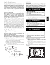
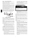
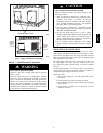
1. Remove all access panels (see Fig. 17).
2. Read and follow instructions on all DANGER, WARNING,
CAUTION, and INFORMATION labels attached to, or
shipped with unit.
3. Make the following inspections:
a. Inspect for shipping and handling damages, such as
broken lines, loose parts, disconnected wires, etc.
b. Inspect for oil at all refrigerant tubing connections and
on unit base. Detecting oil generally indicates a
refrigerant leak. Leak test all refrigerant tubing
connections using electronic leak detector, or
liquid--soap solution. If a refrigerant leak is detected, see
following Check for Refrigerant Leaks section.
c. Inspect all field-- and factory--wiring connections. Be
sure that connections are completed and tight.
d. Ensure wires do not touch refrigerant tubing or sharp
sheet metal edges.
e. Inspect coil fins. If damaged during shipping and
handling, carefully straighten fins with a fin comb.
4. Verify the following conditions:
a. Make sure that condensate drain pan and trap are filled
with water to ensure proper drainage.
b. Make sure that all tools and miscellaneous loose parts
have been removed.
START--UP
Step 1 — Check for R efrigerant Leaks
Proceed as follows to locate and repair a r efrigerant leak and to
charge the unit:
1. Locate leak and make sure that refrigerant system pressure
has been relieved and reclaimed from both high-- and
low--pressure ports.
2. Repair leak following accepted practices.
NOTE: Install a filter drier whenever the system has been opened
for repair .
3. Add a small charge of Puron (R--410A) refrigerant vapor to
system and leak--test unit.
4. Recover refrigerant from system and evacuate to 500
microns if no additional leaks are found.
5. Charge unit with Puron (R--410A) refrigerant, using an
accurate scale. Refer to unit rating plate for required charge.
Step 2 — Start--Up Cooling Section And Make
Adjustments
Complete the required procedures given in the Pre-- Start--Up
section before starting the unit. Do not jumper any safety devices
when operating the unit. Do not operate the unit when the outdoor
temperature is below 40°F(4°C) (unless accessory low--ambient
kit is installed). Do not rapid cycle the compressor. Allow 5
minutes between “on” cycles to prevent compressor damage.
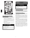
CHECKING COOLING CONTROL OPERATION
Start and check the unit for proper cooling control operation as
follows:
1. Place room thermostat SYSTEM switch in OFF position.
Observe that blower motor starts when FAN switch is
placed in ON position and shuts down when FAN switch is
placed in AUTO position.
2. Place SYSTEM switch in COOL position and F AN s witch
in AUTO position. Set cooling control below room
temperature. Observe that compressor, condenser fan, and
evaporator blower motors start. Observe that compressor
and outdoor fan shut down when control setting is satisfied
and that indoor blower shuts down after 90 second fan time
delay expires.
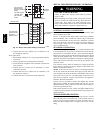
IMPORTANT: Three--phase, scroll compressors are direction
oriented. Unit must be checked to ensure proper compressor
3--phase power lead orientation. If not corrected within 5 minutes,
the internal protector will shut off the compressor. The 3--phase
power leads to the unit must be reversed to correct rotation. When
turning backwards, the dif ference between compressor suction a nd
discharge pressures may be minimal.
CHECKING AND ADJUSTING REFRIGERANT
CHARGE
The refrigerant system is fully charged with Puron (R--410A)
refrigerant and is tested and factory sealed.
NOTE: Adjustment of the refrigerant charge is not required
unless the unit is suspected of not having the proper Puron
(R--410A) charge.
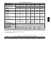
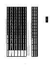
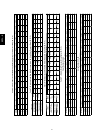
A subcooling charging chart is attached to the inside of the
compressor access panel (see Fig. 17). The chart i ncludes the
required liquid line temperature at given discharge line pressures
and outdoor ambient temperatures.
An accurate thermocouple-- or thermistor--type thermometer, and a
gauge manifold are required when using the subcooling charging
method for evaluating the unit charge. Do not use mercury or small
dial--type thermometers because they are not adequate for this type
of measurement.
NOTE: Allow system to operate for a minimum of 15 minutes
before checking or adjusting refrigerant charge.
IMPORTANT: When evaluating the refrigerant charge, an
indicated adjustment to the specified factory char ge must always be
very minimal. If a substantial adjustment is indicated, an abnormal
condition exists somewhere in the cooling system, such as
insuf ficient airflow across either coil or both coils.
50VL--A