


6
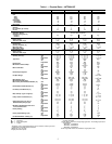
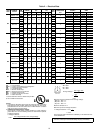
Table 1 — Physical Data — 48TF004-007 (cont)
LEGEND
*Evaporator coil fin material/condenser coil fin material. Contact your local
representative for details about coated fins.
†Weight of 14-in. roof curb.
**Single phase/three-phase.
††Rollout switch lockout is manually reset by interrupting power to unit or
resetting thermostat.
|| Single-phase units have a single-stage gas valve. The heating input values
are as follows:
48TFF004, 115,000 Btuh
48TFF005, 150,000 Btuh
48TFF006, 150,000 Btuh
NOTE: High-static motor not available on single-phase units.
UNIT SIZE 48TF E/F/M/N004 D/E/F/L/M/N005 D/E/F/L/M/N006 D/E/F007
FURNACE SECTION
Rollout Switch Cutout
Temp (F)†† 195 195 195 195
Burner Orifice Diameter
(in. ...drill size)
Natural Gas Std TFD — .113...33 .113...33 .113...33
TFE .113...33 .113...33 .113...33 .113...33
TFF .113...33 .129...30 .129...30 .129...30
TFL — .102...38 .102...38 —
TFM .102...38 .102...38 .102...38 —
TFN .102...38 .116...32 .116...32 —
Liquid Propane Alt TFD — .089...43 .089...43 .089...43
TFE .089...43 .089...43 .089...43 .089...43
TFF .089...43 .102...38 .102...38 .102...38
TFL — .082...45 .082...45 —
TFM .082...45 .082...45 .082...45 —
TFN .082...45 .089...43 .089...43 —
Thermostat Heat Anticipator
Setting (amps)
208/230 v and 575 Stage 1 .14 .14 .14 .14
Stage 2 .14 .14 .14 .14
460 v Stage 1 .14 .14 .14 .14
Stage 2 .14 .14 .14 .14
Gas Input (Btuh)|| Stage 1 TFD — 72,000 72,000 72,000
TFE 72,000 115,000 115,000 115,000
TFF 82,000 120,000 120,000 120,000
TFL — 60,000 60,000 —
TFM 60,000 90,000 90,000 —
TFN 90,000 120,000 120,000 —
Stage 2
(3-phase units)
TFF 115,000 150,000 150,000 150,000
Efficiency (Steady
State) (%) 80 80 80 80
Temperature Rise Range TFD — 25-55 25-55 25-55
TFE 25-55 35-65 35-65 35-65
TFF 55-85 50-80 50-80 50-80
TFL — 20-50 20-50 —
TFM 20-50 30-60 30-60 —
TFN 30-60 40-70 40-70 —
Manifold Pressure (in. wg)
Natural Gas Std 3.5 3.5 3.5 3.5
Liquid Propane Alt 3.5 3.5 3.5 3.5
Gas Valve Quantity 1111
Gas Valve Pressure Range
Psig 0.180-0.487 0.180-0.487 0.180-0.487 0.180-0.487
in. wg 5.0-13.5 5.0-13.5 5.0-13.5 5.0-13.5
Field Gas Connection
Size (in.)
1
/
2
1
/
2
1
/
2
1
/
2
HIGH-PRESSURE SWITCH (psig)
Standard Compressor 450 ± 50 500 ± 50
Internal Relief (Differential)
Cutout 428 428
Reset (Auto.) 320 320
LOSS-OF-CHARGE (LOW-
PRESSURE SWITCH) (psig)
7 ± 3
Cutout
Reset (Auto.) 22 ± 7
FREEZE PROTECTION
THERMOSTAT (F)
Opens 30 ± 5
Closes 45 ± 5
OUTDOOR-AIR INLET SCREENS Cleanable
Quantity...Size (in.) 1...20 x 24 x 1
RETURN-AIR FILTERS Throwaway
Quantity...Size (in.) 2...16 x 25 x 2
Al — Aluminum
Bhp — Brake Horsepower
Cu — Copper