


38
HEATING, UNITS WITH ECONOMIZER — When the
thermostat calls for heating, terminal W1 is energized. To pre-
vent thermostat short-cycling, the unit is locked into the Heat-
ing mode for at least 1 minute when W1 is energized. The
induced-draft motor is energized and the burner ignition se-
quence begins. The indoor (evaporator) fan motor (IFM) is en-
ergized 45 seconds after a flame is ignited and the damper
moves to the minimum position. On units equipped for two
stages of heat, when additional heat is needed, W2 energized
and the high-fire solenoid on the main gas valve (MGV) is en-
ergized. When the thermostat is satisfied and W1 is deener-
gized, the IFM stops after a 45-second time-off delay. The
economizer damper then moves to the fully closed position.
When using continuous fan, the damper will remain in the min-
imum position.
SERVICE
Cleaning —
Inspect unit interior at the beginning of
heating and cooling season and as operating conditions
require.
EVAPORATOR COIL
1. Turn unit power off and install lockout tag. Remove
evaporator coil access panel.
2. If economizer or two-position damper is installed, re-
move economizer by disconnecting Molex plug and re-
moving mounting screws. Refer to accessory economizer
installation instructions or Optional Economizer sections
on pages 12 and 14 for more details.
3. Slide filters out of unit.
4. Clean coil using a commercial coil cleaner or dishwasher
detergent in a pressurized spray canister. Wash both sides
of coil and flush with clean water. For best results, back-
flush toward return-air section to remove foreign materi-
al. Flush condensate pan after completion.
5. Reinstall economizer and filters.
6. Reconnect wiring.
7. Replace access panels.
CONDENSER COIL — Inspect coil monthly. Clean con-
denser coil annually, and as required by location and outdoor
air conditions.
One-Row Coils (Size 004)
— Wash coil with commercial
coil cleaner. It is not necessary to remove top panel.
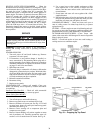
2-Row Coils (Sizes 005-007)
Clean coil as follows:
1. Turn off unit power and install lockout tag.
2. Remove top panel screws on condenser end of unit.
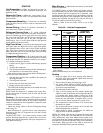
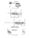
3. Remove condenser coil corner post. See Fig. 42. To hold
top panel open, place coil corner post between top panel
and center post. See Fig. 43.
4. Remove screws securing coil to compressor plate and
compressor access panel.
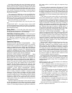
5. Remove fastener holding coil sections together at return
end of condenser coil. Carefully separate the outer coil
section 3 to 4 in. from the inner coil section. See Fig. 44.
6. Use a water hose or other suitable equipment to flush
down between the 2 coil sections to remove dirt and
debris. Clean the outer surfaces with a stiff brush in the
normal manner.
7. Secure inner and outer coil rows together with a field-
supplied fastener.
8. Reposition the outer coil section and remove the coil cor-
ner post from between the top panel and center post. Re-
install the coil corner post and replace all screws.
CONDENSATE DRAIN — Check and clean each year at
start of cooling season. In winter, keep drain dry or protect
against freeze-up.
FILTERS — Clean or replace at start of each heating and cool-
ing season, or more often if operating conditions require it. Re-
placement filters must be same dimensions as original filters.
OUTDOOR-AIR INLET SCREEN — Clean screen with
steam or hot water and a mild detergent. Do not use disposable
filters in place of screen.
BELTS — Check belt tension at least once each heating or
cooling season or as conditions require.
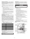
When servicing unit, shut off all electrical power to unit
and install lockout tag to avoid shock hazard or injury from
rotating parts.
Fig. 42 — Cleaning Condenser Coil
Fig. 43 — Propping Up Top Panel