


4
Unit may be installed directly on wood flooring or on
Class A, B, or C roof-covering material when roof curb is used.
Although unit is weatherproof, guard against water from
higher level runoff and overhangs.
Flue vent discharge must have a minimum horizontal clear-
ance of 4 ft from electric and gas meters, gas regulators, and
gas relief equipment.
Minimum distance between unit and other electrically live
parts is 48 inches.
Flue gas can deteriorate building materials. Orient unit such
that flue gas will not affect building materials.
Adequate combustion-air space must be provided for proper
operation of this equipment. Be sure that installation complies
with all local codes and Section 5.3, Air for Combustion and
Ventilation, NFGC (National Fuel Gas Code), and ANSI
(American National Standards Institute) Z223.1, and NFPA
(National Fire Protection Association) 54 TIA-54-84-1.
In Canada, installation must be in accordance with the
CAN1-B149 installation codes for gas burning appliances.
After unit is in position, remove rigging skids and shipping
materials.
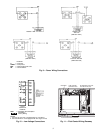
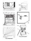
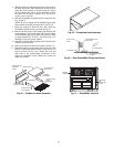
Step 5 — Install Flue Hood —
Flue hood is shipped
screwed to the basepan beside the burner compartment access
panel. Remove from shipping location and using screws pro-
vided, install flue hood and screen in location shown in Fig. 7.
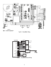
Step 6 — Install Gas Piping —
Unit is equipped for
use with type of gas shown on nameplate. Refer to local build-
ing codes, or in the absence of local codes, to ANSI Z223.1 en-
titled National Fuel Gas Code. In Canada, installation must be
in accordance with the CAN1.B149.1 and CAN1.B149.2 in-
stallation codes for gas burning appliances.
For natural gas applications, gas pressure at unit gas con-
nection must not be less than 4 in. wg or greater than
13.0 in. wg while unit is operating. On 48TF005,006,007 high
heat units, the gas pressure at unit gas connection must not be
less than 5 in. wg or greater than 13 in. wg while the unit is op-
erating. For propane applications, the gas pressure must not
be less than 5 in. wg or greater than 13 in. wg at the unit
connection.
Size gas supply piping for 0.5 in. wg maximum pressure
drop. Do not use supply pipe smaller than unit gas connection.
Support gas piping as shown in the table in Fig. 8. For exam-
ple, a
3
/
4
-in. gas pipe must have one field-fabricated support
beam every 8 ft. Therefore, an 18-ft long gas pipe would have a
minimum of 2 support beams, a 48-ft long pipe would have a
minimum of 6 support beams.
See Fig. 8 for typical pipe guide and locations of external
manual main shutoff valve.
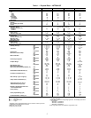
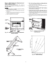
MAXIMUM ALLOWABLE
DIFFERENCE (in.)
A-B B-C A-C
0.5 1.0 1.0
Fig. 3 — Unit Leveling Tolerances
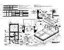
N
OTE: Drain plug is shown in factory-installed position.
Fig. 4 — Condensate Drain Connection
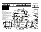
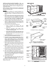
NOTES:
1. Dimensions in ( ) are in millimeters.
2. Hook rigging shackles through holes in base rail, as shown in detail “A.’
Holes in base rails are centered around the unit center of gravity. Use
wooden top skid when rigging to prevent rigging straps from damaging unit.
3. Unit weights do not include economizer. See Table 1 for economizer
weights.
All panels must be in place when rigging.
Fig. 5 — Rigging Details
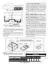
UNIT
MAX WEIGHT “A” “B” “C”
Lb Kg in. mm in. mm in. mm
48TFE,TFF,TFM,TFN004 510 231
73.69 1872 37.50 953 33.35 845
48TFD,TFE,TFF,TFL,TFM,TFN005 520 236
48TFD,TFE,TFF,TFL,TFM,TFN006 540 245
48TFD,TFE,TFF007 615 279