


36
START-UP
Unit Preparation —
Make sure that unit has been in-
stalled in accordance with these installation instructions and
applicable codes.
Return-Air Filters —
Make sure correct filters are in-
stalled in filter tracks. See Table 1. Do not operate unit without
return-air filters.
Compressor Mounting —
Compressors are internally
spring mounted. Do not loosen or remove compressor hold-
down bolts.
Internal Wiring —
Check all electrical connections in
unit control boxes. Tighten as required.
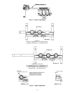
Refrigerant Service Ports —
To service refrigerant
service ports, remove compressor access panel. Each unit sys-
tem has 4 Schrader-type service gage ports: one on the suction
line, one on the liquid line, and two on the compressor dis-
charge line. Be sure that caps on the ports are tight. One
Schrader-type valve is located under both the high-pressure
switch and the low-pressure switch.
High Flow Valves —
Located on the compressor hot gas
and suction tubes are High Flow Valves. Large black plastic
caps distinguish these valves with o-rings located inside the
caps. These valves cannot be accessed for service in the field.
Ensure the plastic caps are in place and tight or the possibility
of refrigerant leakage could occur.
Compressor Rotation —
On 3-phase units with scroll
compressors, it is important to be certain compressor is rotating
in the proper direction. To determine whether or not compres-
sor is rotating in the proper direction:
1. Connect service gages to suction and discharge pressure
fittings.
2. Energize the compressor.
3. The suction pressure should drop and the discharge pres-
sure should rise, as is normal on any start-up.
If the suction pressure does not drop and the discharge pres-
sure does not rise to normal levels:
1. Note that the evaporator fan is probably also rotating in
the wrong direction.
2. Turn off power to the unit.
3. Reverse any two of the unit power leads.
4. Reapply power to the compressor.
The suction and discharge pressure levels should now move
to their normal start-up levels.
NOTE: When the compressor is rotating in the wrong direc-
tion, the unit makes an elevated level of noise and does not
provide cooling.
Cooling —
Set space thermostat to OFF position. To start
unit, turn on main power supply. Set system selector switch at
COOL position and fan switch at AUTO. position. Adjust ther-
mostat to a setting below room temperature. Compressor starts
on closure of contactor.
Check unit charge. Refer to Service, Refrigerant Charge
section, page 39.
Reset thermostat at a position above room temperature.
Compressor will shut off. Evaporator fan will shut off after
30-second delay.
TO SHUT OFF UNIT — Set system selector switch at OFF
position. Resetting thermostat at a position above room tem-
perature shuts unit off temporarily until space temperature ex-
ceeds thermostat setting.
Main Burners —
Main burners are factory set and should
require no adjustment.
TO CHECK ignition of main burners and heating controls,
move thermostat set point above room temperature and verify
that the burners light and evaporator fan is energized. After
ensuring that the unit continues to heat the building, lower the
thermostat setting below room temperature and verify that the
burners and evaporator fan turn off. (Fan will turn off only if
fan selector switch is in the AUTO. position.)
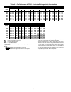
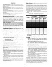
Refer to Table 30 for the correct orifice to use at high
altitudes.
Table 30 — Altitude Compensation*
*As the height above sea level increases, there is less oxygen per
cubic foot of air. Therefore, heat input rate should be reduced at
higher altitudes.
†Orifices available through your Carrier distributor.
Heating
1. Purge gas supply line of air by opening union ahead of
gas valve. If gas odor is detected, tighten union and wait
5 minutes before proceeding.
2. Turn on electrical supply and manual gas valve.
3. Set system switch selector at HEAT position and fan
switch at AUTO. or ON position. Set heating temperature
lever above room temperature.
4. The induced-draft motor will start.
5. After a call for heating, the main burners should light
within 5 seconds. If the burner does not light, then there is
a 22-second delay before another 5-second try. If the
burner still does not light, the time delay is repeated. If the
burner does not light within 15 minutes, there is a lock-
out. To reset the control, break the 24-v power to W1.
6. The evaporator-fan motor will turn on 45 seconds after
the burners are ignited.
7. The evaporator-fan motor will turn off 45 seconds after
thermostat temperature is satisfied.
8. Adjust airflow to obtain a temperature rise within the
range specified on the unit nameplate.
NOTE: The default value for the evaporator-fan motor ON/
OFF delay is 45 seconds. The Integrated Gas Unit Controller
(IGC) modifies this value when abnormal limit switch cycles
occur. Based upon unit operating conditions, the ON delay can
be reduced to 0 seconds and the OFF delay can be extended to
180 seconds. When one flash of the LED is observed, the
evaporator-fan ON/OFF delay has been modified.
ELEVATION
(ft)
74,000 AND 115,000
BTUH NOMINAL
INPUT
150,000 BTUH
NOMINAL INPUT
Natural
Gas
Orifice
Size†
Liquid
Propane
Orifice
Size†
Natural
Gas
Orifice
Size†
Liquid
Propane
Orifice
Size†
0-2,000
33 43 30 38
2,000
34 43 30 39
3,000
35 44 31 40
4,000
36 44 32 41
5,000
36 44 33 42
6,000
37 45 34 43
7,000
37 45 35 43
8,000
38 46 36 44
9,000
39 47 37 44
10,000
41 48 38 45
11,000
43 48 39 45
12,000
44 49 40 46
13,000
44 49 41 47
14,000
45 50 42 47