


Hot Gas Bypass — An optional hot gas bypass system
may be factory installed on circuit no. 1. This system will
introduce discharge vapor from the compressor discharge line
into the distributors and evaporator coil circuits on circuit
no. 1 when suction pressures drop to damaging levels. No
field adjustments of the hot gas bypass valve should be
required.
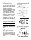
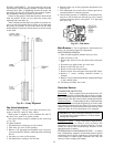
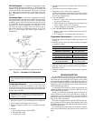
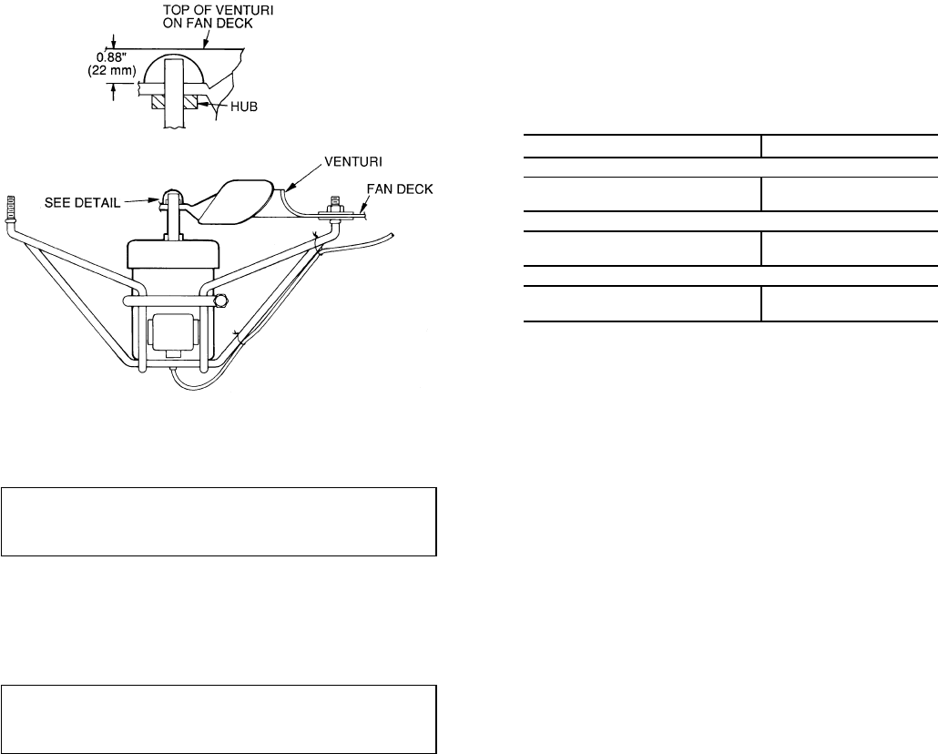
Condenser Fans — Each fan is supported by a formed
wire mount bolted to fan deck and covered with a wire guard.
The exposed end of the fan motor shaft is protected from
weather by grease. If fan motor must be removed for service
or replacement, be sure to regrease fan shaft and reinstall
fan guard. For proper performance, fan should be
7
⁄
8
in.
(22 mm) below top of venturi on the fan deck to top of
the fan hub. (See Fig. 64.) Tighten set screws to 15 ± 1 ft-lbs
(20 ± 1.3 N-m). Figure 64 shows proper position of
mounted fan.
IMPORTANT: Check for proper fan rotation (clock-
wise viewed from above). If necessary to reverse, switch
leads.
Compressor Removal — Access to the pump end of
the compressor is from the compressor side of the unit.
Access to the motor end of the compressor is from the inside
of the unit. All compressors can be removed from the com-
pressor side of the unit.
IMPORTANT:All compressor mounting hardware and
support brackets removed during servicing must be re-
installed prior to start-up.
1. Disconnect power to unit; lockout power to compressor.
2. Close suction and discharge service valves.
3. Relieve refrigerant pressure into a refrigerant recovery
system.
4. Remove:
a. Fan-cycling pressure switch (FCPS)
b. High-pressure switch
c. Low-pressure switch
5. Disconnect power wires at terminal box and disconnect
conduit.
6. Disconnect wires from crankcase heater.
7. Disconnect service valves from compressor.
NOTE: On units with 2 compressors per circuit, discon-
nect both oil equalizer lines located on the motor barrel
and on the oil pump sump.
8. Units 48/50MP62L:
a. Remove 4 large screws securing compressor mount-
ing pan to unit base rail.
b. Slide compressor (on mounting pan) to outside of unit
frame; support and/or lower to ground.
c. Unbolt compressor from mounting pan and remove.
9. Units 48/50MP70M,82N,90P,10R:
a. Remove 4 large screws securing compressor to the com-
pressor rails.
b. Lift compressor off mounting bolts and remove.
Compressor Replacement — Perform the following:
1. Reverse procedure in Compressor Removal section to end
of Step 4.
2. Reinstall service valves and safety switches, and tighten
to torques as listed:
TORQUE COMPRESSOR(S)
Tighten discharge valves to —
20-25 ft-lbs ( 27- 34 N-m) 06E-250
80-90 ft-lbs (109-122 N-m) 06E-265,275,299
Tighten suction valves to —
80- 90 ft-lbs (109-122 N-m) 06E-250
90-120 ft-lbs (122-163 N-m) 06E-265,275,299
Tighten the following fittings as specified —
120 in.-lbs (13.5 N-m) High-Pressure Switch
120 in.-lbs (13.5 N-m) Low-Pressure Switch
3. Leak-check and evacuate system, reclaim refrigerant.
4. Recharge system per pre-start-up and start-up sequences.
Recheck oil levels.
5. Energize crankcase heater for 24 hours prior to restart of
system.
TROUBLESHOOTING
The 48/50MP units provide extensive troubleshooting in-
formation to service personnel through the use of status codes
and alarm and alert codes from the control system, which
are displayed on the unit HSIO or through the use of Service
Tool or CCN Building Supervisor. For more information on
diagnostics, codes, and possible causes, refer to the Controls
and Troubleshooting manual.
Use the Quick Test function to check control inputs and
outputs (including economizer actuators). Refer to Controls
and Troubleshooting Guide.
If there are indications of hunting (rapid oscillations) of
control functions (such as duct static pressure or supply air
temperature), or if the response rate is too slow, check the
gain values. Refer to the Control Loop Checkout section on
page 40 for more information.
If the unit is equipped with an optional VFD and the sup-
ply or exhaust fan is not running when required, refer to the
troubleshooting section of the separate VFD technical manual
provided with the unit.
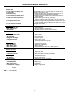
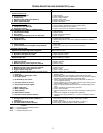
For troubleshooting information on mechanical systems,
refer to the troubleshooting and diagnostics table on the next
page.
NOTE: Fan rotation is clockwise when viewed from top of unit.
Fig. 64 — Condenser Fan Adjustment
55