


KEYPAD AND DISPLAY MODULE (HSIO)
CONFIGURATION
IMPORTANT: The HSIO keypad and display module
is required for initial start-up of these units. All units
are shipped in standby mode, and the HSIO should be
used to change the unit to run mode. Once the unit is
in run mode, the HSIO is not required for normal
operation.
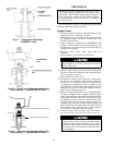
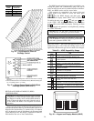
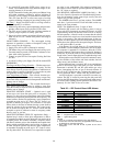
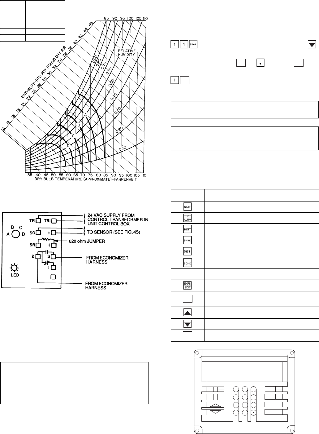
The keypad and display module provides unit function in-
formation at the unit. See Fig. 48. The module consists of a
keypad with 6 function keys, 5 operative keys, 10 numeric
keys (0 through 9), and an alphanumeric 8-character liquid
crystal display (LCD). Key usage is explained in Table 23.
Each function has one or more subfunctions.
The HSIO keypad and display module is installed by con-
necting the power and communication plugs and can be
easily moved from one unit to another. Because of this flex-
ibility, one HSIO can be used for several units.
Unit operation is controlled by the status of the run/
standby mode on the HSIO. To access the mode, press
on the HSIO keypad, and then press .
The HSIO will display either STBY YES or STBY NO.
CLEAR
ENTER
To enable the unit, press or and press while
at the STBY YES display. To disable the unit, press
ENTER
while at the STBY NO display. Clearing an alarm
that has stopped unit operation is accomplished by entering
the STBY YES mode.
IMPORTANT: Use the STBY YES mode when ser-
vicing the unit or running the quick test feature.
IMPORTANT: If remote start function is used, place
LOCAL/REMOTE switch in Local(OFF) position when
ever unit is placed in STBY YES.
SET UNIT TYPE — The correct unit type must be set. The
default unit type is VAV. If the unit is being used in a VAV
application, then the unit type does not need to be changed.
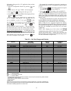
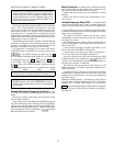
Table 23 — HSIO Keypad Key Usage
FUNCTION
KEYS
USE
Status — To display diagnostic codes and
current operating information about the unit.
Quick Test — To check inputs and outputs for
proper operation.
History — To check most recent alarms.
Service — To enter specific unit configuration
information.
Set Point — To enter operating set points and
day/time information.
Schedule — To enter occupied/unoccupied
schedules for unit operation.
OPERATIVE
KEYS
USE
Expand Display — To display a non-
abbreviated expansion of the display.
CLEAR
Clear — To clear the screen and return to previous
display. Also used to enter data value
of zero.
Up Arrow — To return to previous display position.
Down Arrow — To advance to next display position.
ENTER
To enter data.
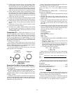
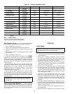
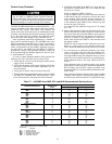
CONTROL
CURVE
CONTROL POINT
(Approx Deg F)
AT 50% RH
A 73
B 68
C 63
D 58
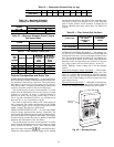
Fig. 46 — Psychrometric Chart for
Enthalpy Control
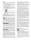
NOTES:
1. Switchesshown inhigh enthalpystate.Terminals 2and3 closeon enthalpy
decrease.
2. Whenstandardeconomizeris usedwithaccessorydifferentialenthalpysen-
sor, set enthalpy control to ‘‘D’’ setting.
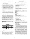
Fig. 47 — Wiring Connections for Solid-State
Enthalpy Sensor (HH57AC077)
1
2
3
4
5
6
7
8
9
0
-
STAT
SET
SCHD
EXPN
EDIT
SRVC
HIST
ALGO
TEST
ALRM
CLEAR
ENTER
Fig. 48 — Keypad and Display Module (HSIO)
36